How to Use clavier 4x4: Examples, Pinouts, and Specs

Introduction
The Clavier 4x4 by AZDelivery is a 4x4 keypad matrix consisting of 16 buttons arranged in a grid. This component is widely used for input in electronic devices, allowing users to enter numerical or alphanumeric data. It is a versatile and cost-effective solution for projects requiring user interaction, such as password entry systems, menu navigation, or custom control panels.
Explore Projects Built with clavier 4x4
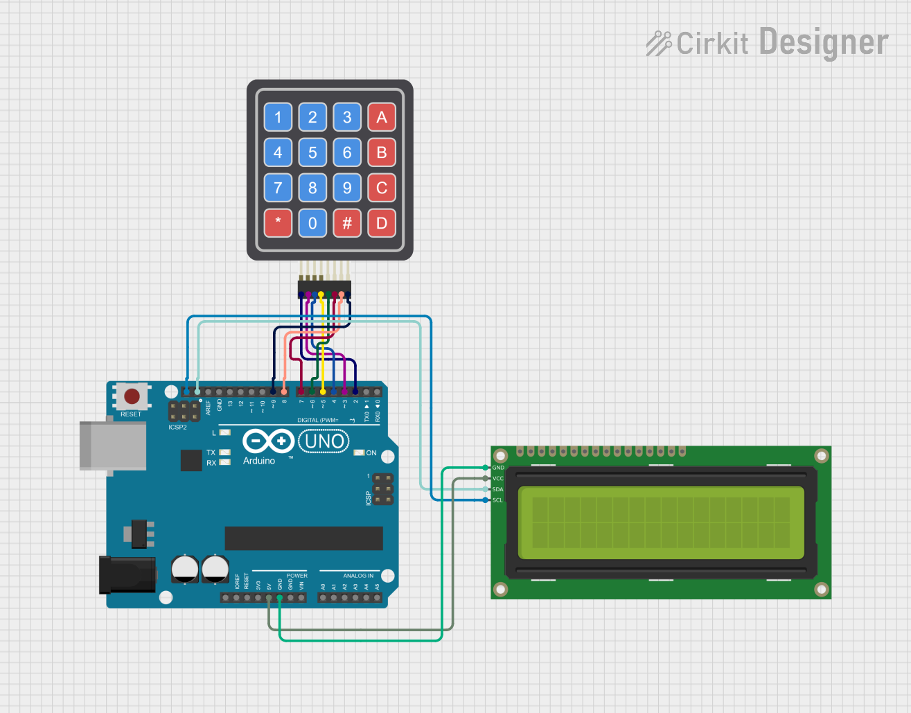

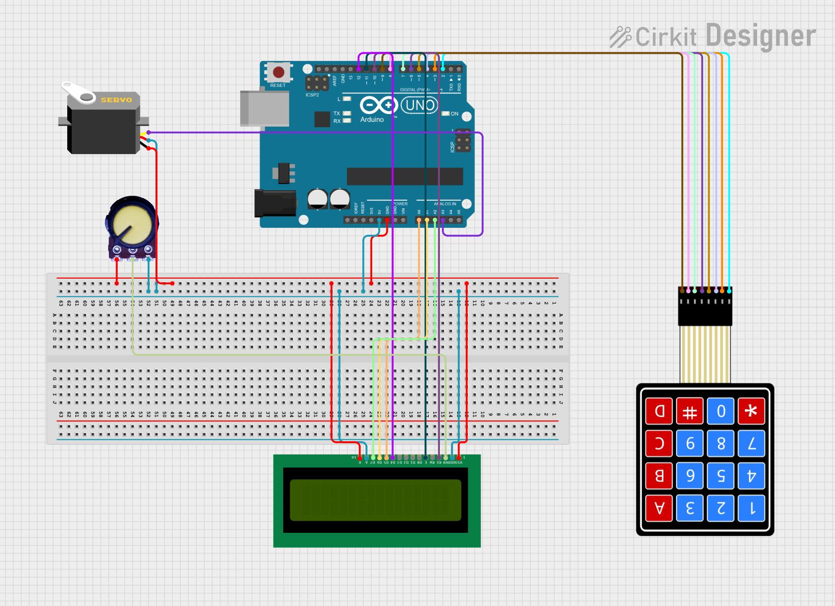
Explore Projects Built with clavier 4x4
Common Applications and Use Cases
- Security systems (e.g., PIN entry for door locks)
- Embedded systems requiring user input
- Calculator or menu navigation interfaces
- Robotics control panels
- Home automation systems
Technical Specifications
The following table outlines the key technical details of the Clavier 4x4 keypad matrix:
| Parameter | Specification |
|---|---|
| Manufacturer | AZDelivery |
| Part ID | Clavier 4x4 |
| Number of Buttons | 16 (4 rows × 4 columns) |
| Operating Voltage | 3.3V to 5V |
| Interface Type | Matrix (row-column scanning) |
| Dimensions | 70mm × 77mm |
| Connector Type | 8-pin header |
| Button Type | Momentary push buttons |
Pin Configuration and Descriptions
The Clavier 4x4 keypad has 8 pins, which correspond to the rows and columns of the matrix. The pinout is as follows:
| Pin Number | Label | Description |
|---|---|---|
| 1 | R1 | Row 1 |
| 2 | R2 | Row 2 |
| 3 | R3 | Row 3 |
| 4 | R4 | Row 4 |
| 5 | C1 | Column 1 |
| 6 | C2 | Column 2 |
| 7 | C3 | Column 3 |
| 8 | C4 | Column 4 |
Usage Instructions
How to Use the Clavier 4x4 in a Circuit
- Wiring the Keypad: Connect the 8 pins of the keypad to your microcontroller. The row pins (R1–R4) and column pins (C1–C4) should be connected to GPIO pins.
- Matrix Scanning: The keypad operates using a row-column scanning technique. The microcontroller sends signals to the rows and reads the columns to detect which button is pressed.
- Pull-Up Resistors: Ensure that the GPIO pins used for the columns are configured with pull-up resistors to avoid floating inputs.
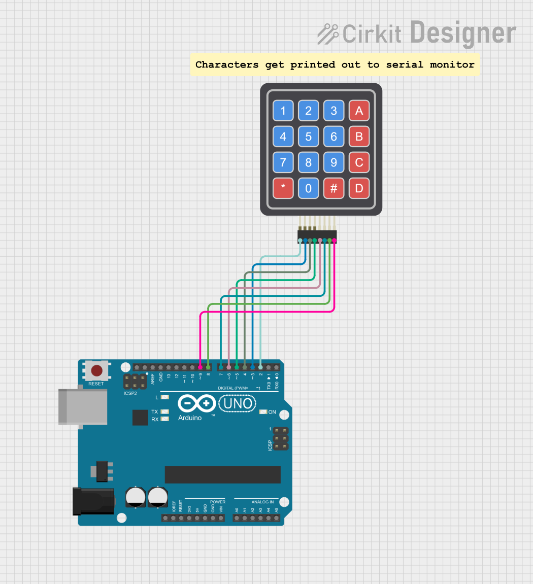
Example: Connecting to an Arduino UNO
Below is an example of how to connect and use the Clavier 4x4 keypad with an Arduino UNO. This example uses the Keypad library, which simplifies matrix scanning.
Circuit Diagram
- Connect the keypad pins R1–R4 to Arduino digital pins 2–5.
- Connect the keypad pins C1–C4 to Arduino digital pins 6–9.
Arduino Code
#include <Keypad.h>

// Define the rows and columns of the keypad
const byte ROWS = 4; // Number of rows
const byte COLS = 4; // Number of columns

// Define the keymap for the keypad
char keys[ROWS][COLS] = {
  {'1', '2', '3', 'A'},
  {'4', '5', '6', 'B'},
  {'7', '8', '9', 'C'},
  {'*', '0', '#', 'D'}
};

// Define the row and column pins connected to the Arduino
byte rowPins[ROWS] = {2, 3, 4, 5}; // R1, R2, R3, R4
byte colPins[COLS] = {6, 7, 8, 9}; // C1, C2, C3, C4

// Create a Keypad object
Keypad keypad = Keypad(makeKeymap(keys), rowPins, colPins, ROWS, COLS);

void setup() {
  Serial.begin(9600); // Initialize serial communication
  Serial.println("Keypad Test: Press a key");
}

void loop() {
  char key = keypad.getKey(); // Get the key pressed
  if (key) {
    Serial.print("Key Pressed: ");
    Serial.println(key); // Print the key to the serial monitor
  }
}
Important Considerations and Best Practices
- Debouncing: The
Keypadlibrary handles debouncing internally, but if you are implementing your own scanning logic, ensure you debounce the inputs to avoid false readings. - Power Supply: Operate the keypad within the specified voltage range (3.3V–5V) to prevent damage.
- Button Press Detection: Avoid pressing multiple buttons simultaneously, as this can cause ghosting (incorrect key detection) unless you implement anti-ghosting techniques.
Troubleshooting and FAQs
Common Issues and Solutions
No Key Press Detected:
- Verify the wiring between the keypad and the microcontroller.
- Ensure the row and column pins are correctly assigned in the code.
- Check for loose connections or damaged wires.
Incorrect Key Press Detected:
- Ensure the keymap in the code matches the physical layout of the keypad.
- Check for ghosting issues if multiple keys are pressed simultaneously.
Floating Inputs:
- Ensure pull-up resistors are enabled for the column pins to avoid floating inputs.
FAQs
Q: Can I use the Clavier 4x4 with a 3.3V microcontroller?
A: Yes, the keypad operates within a voltage range of 3.3V to 5V, making it compatible with 3.3V microcontrollers like the ESP32 or Raspberry Pi Pico.
Q: How do I prevent ghosting when multiple keys are pressed?
A: Use a diode at each button connection to prevent ghosting, or limit the design to single key presses at a time.
Q: Can I use this keypad for alphanumeric input?
A: Yes, the keypad can be programmed to accept alphanumeric input by mapping the keys to desired characters in the code.
This concludes the documentation for the Clavier 4x4 keypad matrix. For further assistance, refer to the AZDelivery product page or community forums.