How to Use TEXAS: Examples, Pinouts, and Specs
It appears there was a misunderstanding regarding the component name. Based on the manufacturer and part ID provided, the correct component is the LT1013CP, which is a dual precision operational amplifier (op-amp) manufactured by Texas Instruments. Below is the detailed documentation for the LT1013CP.
LT1013CP Dual Precision Operational Amplifier
Introduction
The LT1013CP is a dual precision operational amplifier (op-amp) designed by Texas Instruments. It is known for its high accuracy, low offset voltage, and low drift over time and temperature. This makes it an ideal choice for applications requiring precise analog signal processing.
Common Applications
- Instrumentation Amplifiers: For accurate signal amplification in measurement systems.
- Active Filters: Used in signal conditioning circuits.
- Data Acquisition Systems: For precise data collection and processing.
- Medical Instrumentation: Ensures accurate readings in medical devices.
- Sensor Signal Conditioning: Amplifies signals from various sensors.
Technical Specifications
Key Technical Details
| Parameter | Value |
|---|---|
| Supply Voltage Range | ±2V to ±22V |
| Input Offset Voltage | 50µV (typical) |
| Input Bias Current | 0.5nA (typical) |
| Input Offset Current | 0.3nA (typical) |
| Slew Rate | 0.1V/µs |
| Gain Bandwidth Product | 0.8MHz |
| Output Short-Circuit Current | 25mA (typical) |
| Operating Temperature Range | 0°C to 70°C |
| Package Type | 8-Pin PDIP |
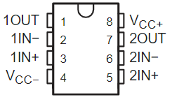
Pin Configuration and Descriptions
| Pin Number | Pin Name | Description |
|---|---|---|
| 1 | OUT A | Output of Op-Amp A |
| 2 | IN- A | Inverting Input of Op-Amp A |
| 3 | IN+ A | Non-Inverting Input of Op-Amp A |
| 4 | V- | Negative Power Supply |
| 5 | IN+ B | Non-Inverting Input of Op-Amp B |
| 6 | IN- B | Inverting Input of Op-Amp B |
| 7 | OUT B | Output of Op-Amp B |
| 8 | V+ | Positive Power Supply |
Usage Instructions
How to Use the Component in a Circuit
Power Supply:
- Connect the positive power supply to pin 8 (V+).
- Connect the negative power supply to pin 4 (V-).
Input Connections:
- For Op-Amp A, connect the input signal to pin 3 (IN+ A) for non-inverting input or pin 2 (IN- A) for inverting input.
- For Op-Amp B, connect the input signal to pin 5 (IN+ B) for non-inverting input or pin 6 (IN- B) for inverting input.
Output Connections:
- The output of Op-Amp A is available at pin 1 (OUT A).
- The output of Op-Amp B is available at pin 7 (OUT B).
Important Considerations and Best Practices
- Decoupling Capacitors: Place decoupling capacitors (0.1µF) close to the power supply pins to filter out noise.
- Input Impedance: Ensure high input impedance to minimize loading effects.
- Feedback Network: Use appropriate feedback resistors to set the desired gain.
- Thermal Management: Ensure proper thermal management to avoid overheating.
Example Circuit with Arduino UNO
Here is an example of how to use the LT1013CP with an Arduino UNO to amplify a sensor signal:
// Example code to read an amplified sensor signal using Arduino UNO

const int sensorPin = A0; // Analog input pin for sensor signal
const int ledPin = 13;    // Digital output pin for LED

void setup() {
  pinMode(ledPin, OUTPUT); // Set LED pin as output
  Serial.begin(9600);      // Initialize serial communication
}

void loop() {
  int sensorValue = analogRead(sensorPin); // Read the sensor value
  Serial.println(sensorValue);             // Print the sensor value to serial monitor

  // Simple threshold to turn on LED if sensor value exceeds 512
  if (sensorValue > 512) {
    digitalWrite(ledPin, HIGH); // Turn on LED
  } else {
    digitalWrite(ledPin, LOW);  // Turn off LED
  }

  delay(100); // Delay for stability
}
Troubleshooting and FAQs
Common Issues and Solutions
No Output Signal:
- Check Power Supply: Ensure that the power supply is connected correctly.
- Verify Connections: Double-check all input and output connections.
Output Signal is Distorted:
- Check Feedback Network: Ensure that the feedback resistors are correctly placed.
- Verify Power Supply Voltage: Ensure that the supply voltage is within the specified range.
High Offset Voltage:
- Check Input Bias Current: Ensure that the input bias current is within the specified range.
- Use Precision Resistors: Use precision resistors to minimize offset voltage.
FAQs
Q1: Can I use the LT1013CP for single-supply operation?
- Yes, the LT1013CP can be used for single-supply operation. Connect the negative power supply pin (V-) to ground.
Q2: What is the maximum output current of the LT1013CP?
- The typical output short-circuit current is 25mA.
Q3: How do I minimize noise in my circuit?
- Use decoupling capacitors close to the power supply pins and ensure proper grounding.
Q4: Can I use the LT1013CP in high-frequency applications?
- The LT1013CP has a gain bandwidth product of 0.8MHz, making it suitable for low to moderate frequency applications.
This documentation provides a comprehensive overview of the LT1013CP dual precision operational amplifier, including its technical specifications, usage instructions, and troubleshooting tips. Whether you are a beginner or an experienced user, this guide will help you effectively utilize the LT1013CP in your projects.
Explore Projects Built with TEXAS
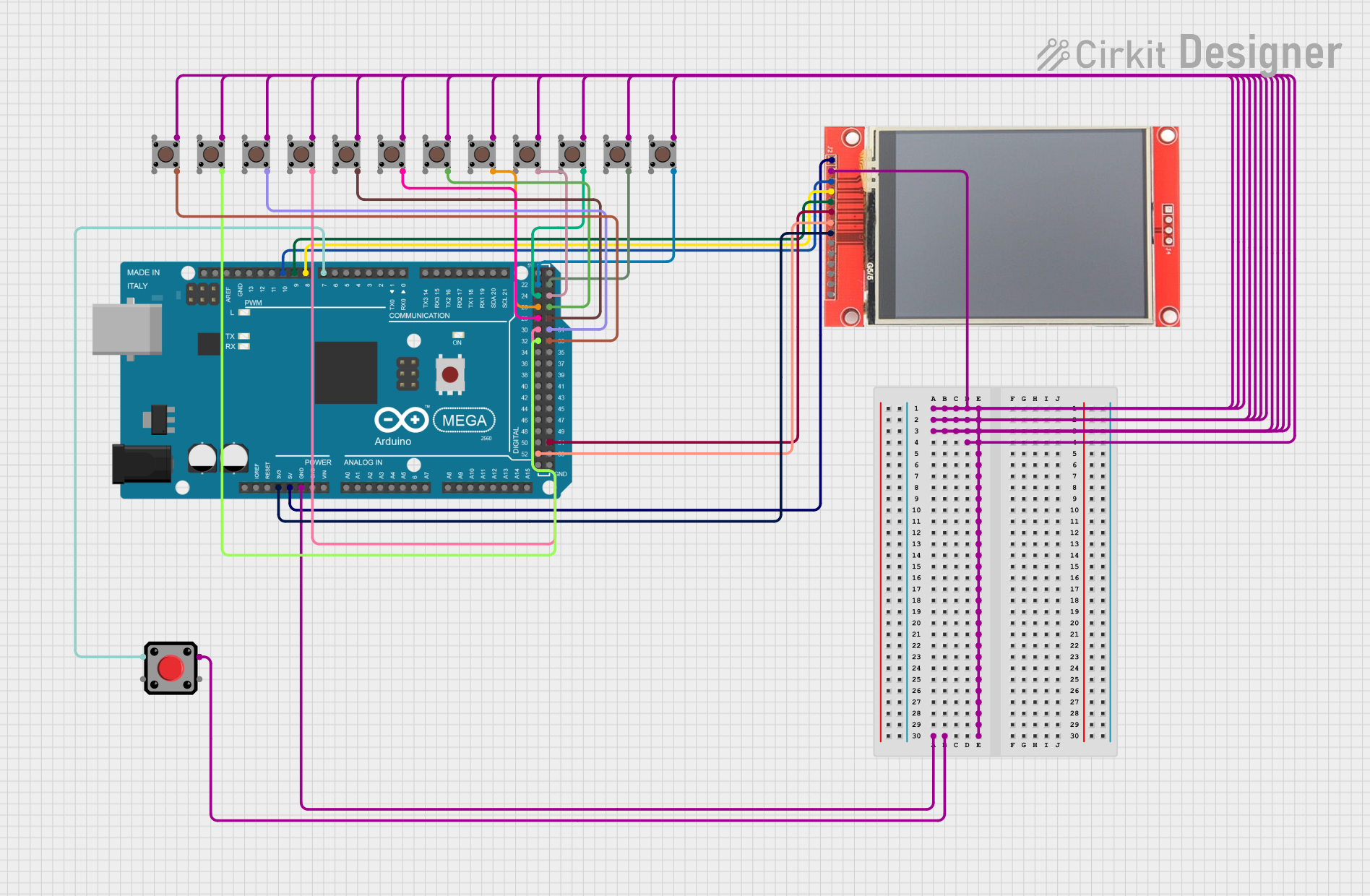

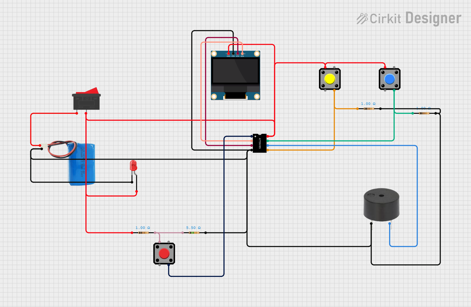
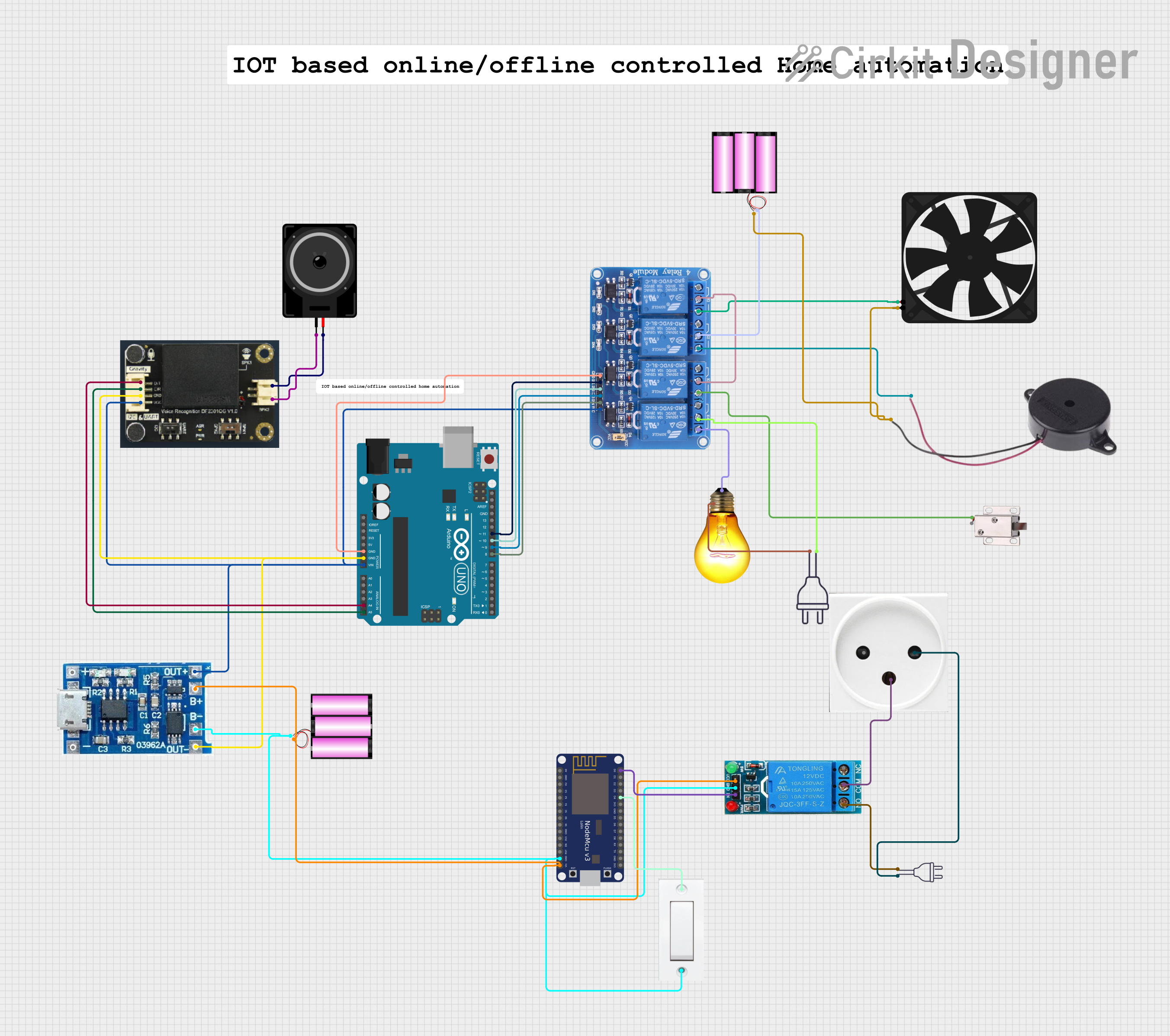
Explore Projects Built with TEXAS