
How to Use Adafruit Feather M0 RFM69: Examples, Pinouts, and Specs
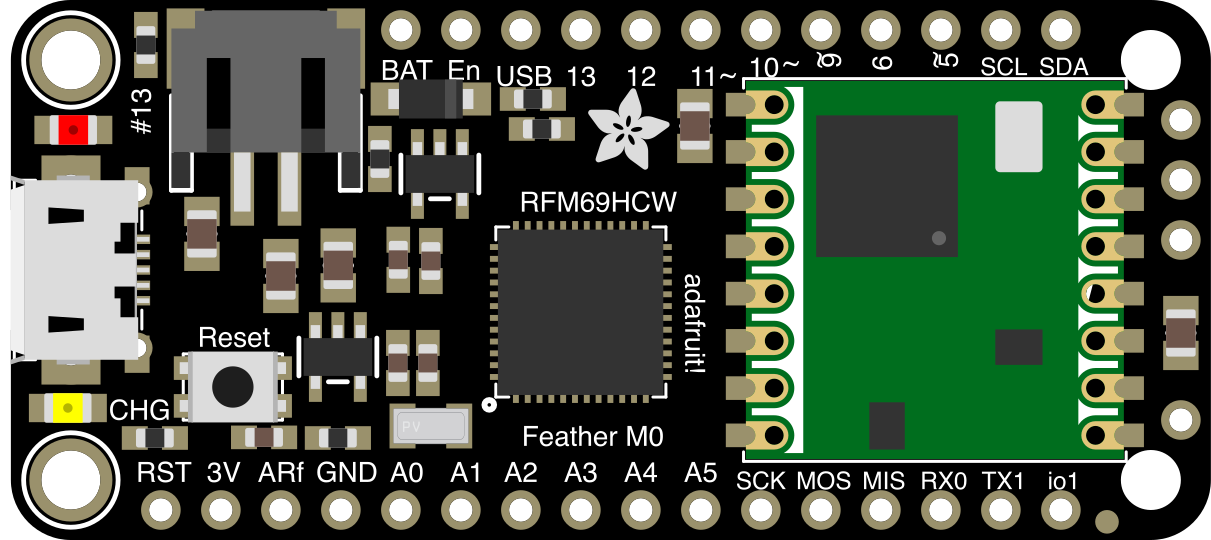
 Design with Adafruit Feather M0 RFM69 in Cirkit Designer
Introduction
The Adafruit Feather M0 RFM69 is a compact and versatile microcontroller board designed for IoT (Internet of Things) applications. It features an ARM Cortex-M0 processor and an integrated RFM69 radio module, enabling low-power wireless communication. This board is part of Adafruit's Feather ecosystem, which supports a wide range of add-ons and peripherals, making it ideal for projects requiring wireless connectivity, sensor integration, and low power consumption.
Explore Projects Built with Adafruit Feather M0 RFM69
 Open Project in Cirkit Designer
 Open Project in Cirkit Designer
 Open Project in Cirkit Designer
 Open Project in Cirkit Designer
Explore Projects Built with Adafruit Feather M0 RFM69
Open Project in Cirkit DesignerOpen Project in Cirkit DesignerOpen Project in Cirkit DesignerOpen Project in Cirkit DesignerCommon Applications and Use Cases
- Wireless sensor networks
- Home automation systems
- Remote data logging
- Environmental monitoring
- IoT prototyping and development
- Low-power wireless communication projects
Technical Specifications
Key Technical Details
| Specification | Value |
|---|---|
| Microcontroller | ATSAMD21G18 ARM Cortex-M0 |
| Operating Voltage | 3.3V |
| Clock Speed | 48 MHz |
| Flash Memory | 256 KB |
| SRAM | 32 KB |
| Wireless Module | RFM69HCW (433 MHz, 868 MHz, or 915 MHz) |
| Communication Protocols | SPI, I2C, UART |
| GPIO Pins | 20 (including analog and PWM-capable pins) |
| Power Supply | USB or LiPo battery (3.7V) |
| Dimensions | 51mm x 23mm x 8mm |
Pin Configuration and Descriptions
| Pin Name | Description |
|---|---|
| VIN | Input voltage pin (3.7V LiPo battery or USB power input) |
| 3V3 | Regulated 3.3V output from the onboard regulator |
| GND | Ground pin |
| A0–A5 | Analog input pins (can also be used as digital GPIO) |
| D0–D13 | Digital GPIO pins (some support PWM output) |
| SDA | I2C data line |
| SCL | I2C clock line |
| MOSI | SPI Master Out Slave In |
| MISO | SPI Master In Slave Out |
| SCK | SPI clock |
| RFM69_CS | Chip select for the RFM69 radio module |
| RFM69_INT | Interrupt pin for the RFM69 module |
| RFM69_RST | Reset pin for the RFM69 module |
| EN | Enable pin for the 3.3V regulator |
| BAT | LiPo battery voltage monitoring pin |
Usage Instructions
How to Use the Component in a Circuit
Powering the Board:
- Connect a 3.7V LiPo battery to the BAT pin or power the board via the USB port.
- The onboard regulator will provide a stable 3.3V to the microcontroller and peripherals.
Connecting Sensors and Peripherals:
- Use the GPIO pins (D0–D13) for digital input/output operations.
- Connect analog sensors to the A0–A5 pins for analog input.
- Use the I2C (SDA, SCL) or SPI (MOSI, MISO, SCK) pins for communication with compatible devices.
Using the RFM69 Radio Module:
- Connect an appropriate antenna to the RFM69 module for wireless communication.
- Configure the RFM69 module using the provided libraries and set the frequency (433 MHz, 868 MHz, or 915 MHz) based on your region.
Programming the Board:
- Connect the board to your computer via USB.
- Use the Arduino IDE or CircuitPython to write and upload code to the board.
Important Considerations and Best Practices
- Ensure the operating voltage of connected peripherals is compatible with the 3.3V logic level of the Feather M0.
- Use a proper antenna for the RFM69 module to maximize wireless range and performance.
- Avoid powering the board via USB and LiPo battery simultaneously to prevent damage.
- When using the RFM69 module, ensure the frequency complies with local regulations.
Example Code for Arduino UNO Integration
Below is an example of how to use the Adafruit Feather M0 RFM69 with the Arduino IDE to send a simple wireless message:
#include <RFM69.h> // Include the RFM69 library

#define RFM69_CS 8    // Chip select pin for RFM69
#define RFM69_INT 3   // Interrupt pin for RFM69
#define RFM69_RST 4   // Reset pin for RFM69
#define NETWORK_ID 100 // Network ID for communication
#define NODE_ID 1      // Node ID for this device
#define RECEIVER_ID 2  // Node ID of the receiver

RFM69 radio; // Create an RFM69 object

void setup() {
  Serial.begin(9600); // Initialize serial communication
  Serial.println("Initializing RFM69...");

  // Initialize the RFM69 module
  if (!radio.initialize(RF69_915MHZ, NODE_ID, NETWORK_ID)) {
    Serial.println("RFM69 initialization failed!");
    while (1); // Halt execution if initialization fails
  }
  Serial.println("RFM69 initialized successfully!");

  // Set encryption key (optional)
  radio.encrypt("sampleEncryptKey");
}

void loop() {
  // Send a message to the receiver
  const char message[] = "Hello, RFM69!";
  if (radio.sendWithRetry(RECEIVER_ID, message, sizeof(message))) {
    Serial.println("Message sent successfully!");
  } else {
    Serial.println("Message sending failed!");
  }

  delay(1000); // Wait 1 second before sending the next message
}
Troubleshooting and FAQs
Common Issues and Solutions
The board is not recognized by the computer:
- Ensure the USB cable is functional and supports data transfer.
- Install the necessary drivers for the Feather M0.
RFM69 module is not communicating:
- Verify the antenna is properly connected.
- Check the frequency settings and ensure they match the receiver's configuration.
Power issues when using a LiPo battery:
- Ensure the battery is charged and connected securely.
- Check the BAT pin voltage to confirm the battery is supplying power.
Code upload fails:
- Double-check the selected board and port in the Arduino IDE.
- Press the reset button on the Feather M0 before uploading the code.
FAQs
Can I use the Feather M0 RFM69 with CircuitPython?
Yes, the Feather M0 supports CircuitPython. You can install CircuitPython firmware and use Adafruit's libraries for development.What is the maximum wireless range of the RFM69 module?
The range depends on the antenna and environment but can reach up to 500 meters in open areas.Can I power the board with both USB and a LiPo battery?
Yes, the board automatically switches between USB and battery power, but avoid connecting both power sources simultaneously during testing.Is the RFM69 module compatible with LoRa?
No, the RFM69 uses FSK modulation and is not compatible with LoRa, which uses a different modulation scheme.