How to Use multi-turn potentiometer: Examples, Pinouts, and Specs
Introduction
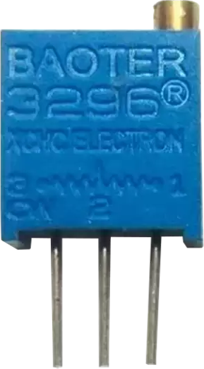
A multi-turn potentiometer, also known as a precision potentiometer, is a variable resistor designed to provide fine adjustments of resistance. Unlike standard potentiometers, which typically allow for a single rotation, multi-turn potentiometers require multiple rotations of the shaft to traverse their full resistance range. This design enables precise control, making them ideal for applications where accuracy is critical.
Explore Projects Built with multi-turn potentiometer
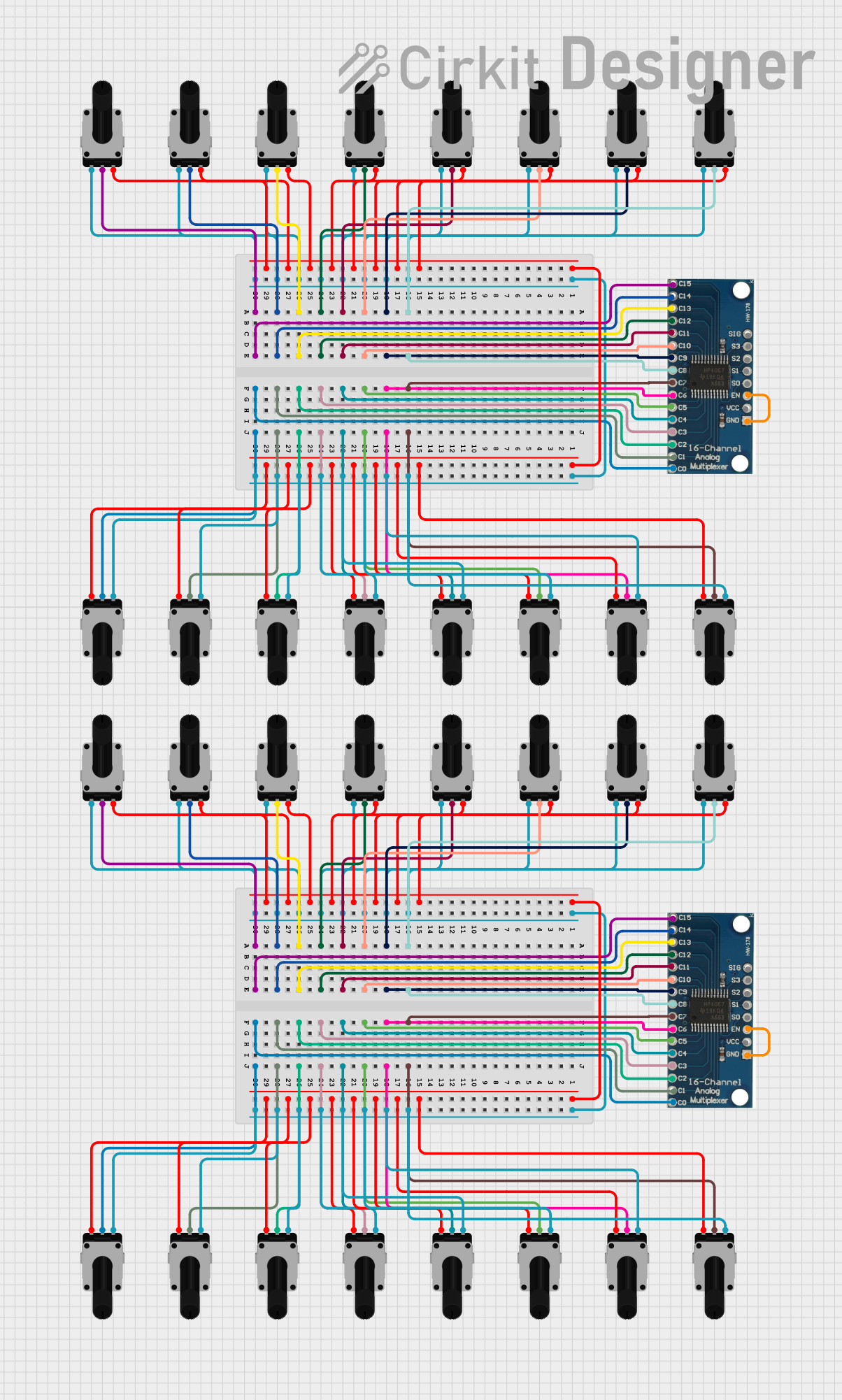


Explore Projects Built with multi-turn potentiometer
Common Applications and Use Cases
- Volume Control: Used in audio equipment for precise volume adjustments.
- Tuning Circuits: Common in radio frequency (RF) circuits for fine-tuning.
- Calibration: Used in test equipment and instrumentation for accurate calibration.
- Industrial Controls: Employed in machinery for setting precise operational parameters.
- Sensor Adjustment: Used to fine-tune sensor outputs in various systems.
Technical Specifications
Below are the key technical details for the multi-turn potentiometer with manufacturer part ID: 10K.
General Specifications
- Manufacturer: Others
- Part ID: 10K
- Resistance Range: 0 Ω to 10 kΩ
- Number of Turns: Typically 10 turns
- Power Rating: 0.5 W (500 mW)
- Tolerance: ±5%
- Temperature Range: -55°C to +125°C
- Adjustment Type: Screwdriver slot or knob
- Mounting Type: Through-hole or panel mount
Pin Configuration and Descriptions
The multi-turn potentiometer typically has three pins, as described in the table below:
| Pin Number | Name | Description |
|---|---|---|
| 1 | Terminal 1 | One end of the resistive element. Connect to the circuit's reference point. |
| 2 | Wiper | The adjustable terminal. Resistance between this pin and the others varies. |
| 3 | Terminal 2 | The other end of the resistive element. Connect to the circuit's load. |
Usage Instructions
How to Use the Component in a Circuit
- Identify the Pins: Locate the three pins (Terminal 1, Wiper, and Terminal 2) on the potentiometer.
- Connect the Circuit:
- Connect Terminal 1 to the reference voltage (e.g., ground or Vcc).
- Connect Terminal 2 to the load or the other voltage source.
- Connect the Wiper to the input of the circuit where the variable resistance is required.
- Adjust the Resistance:
- Use a screwdriver or knob to rotate the shaft.
- Turning the shaft clockwise typically increases the resistance between Terminal 1 and the Wiper, while decreasing the resistance between Terminal 2 and the Wiper.
Important Considerations and Best Practices
- Avoid Overturning: Do not force the shaft beyond its maximum number of turns, as this can damage the internal mechanism.
- Power Rating: Ensure the power dissipation does not exceed the rated 0.5 W to prevent overheating.
- Stable Mounting: Secure the potentiometer firmly to avoid mechanical stress during operation.
- Debouncing: If used in digital circuits, consider adding a capacitor to reduce noise caused by wiper movement.
Example: Using with Arduino UNO
The multi-turn potentiometer can be used with an Arduino UNO to read analog values. Below is an example code snippet:
// Arduino code to read the resistance value of a multi-turn potentiometer
// and display it on the Serial Monitor.

const int potPin = A0; // Connect the wiper (Pin 2) to analog pin A0

void setup() {
  Serial.begin(9600); // Initialize serial communication at 9600 baud
}

void loop() {
  int potValue = analogRead(potPin); // Read the analog value (0-1023)
  float voltage = potValue * (5.0 / 1023.0); // Convert to voltage (0-5V)

  // Print the resistance value to the Serial Monitor
  Serial.print("Analog Value: ");
  Serial.print(potValue);
  Serial.print(" | Voltage: ");
  Serial.print(voltage);
  Serial.println(" V");

  delay(500); // Wait for 500ms before the next reading
}
Troubleshooting and FAQs
Common Issues and Solutions
No Change in Resistance:
- Cause: The wiper pin (Pin 2) is not connected properly.
- Solution: Verify the connections and ensure the wiper is connected to the circuit.
Inconsistent Readings:
- Cause: Dust or debris inside the potentiometer.
- Solution: Clean the potentiometer using compressed air or replace it if damaged.
Overheating:
- Cause: Exceeding the power rating of 0.5 W.
- Solution: Reduce the current or voltage applied to the potentiometer.
Shaft Not Turning Smoothly:
- Cause: Mechanical wear or damage.
- Solution: Replace the potentiometer if the shaft is stuck or difficult to turn.
FAQs
Q: Can I use this potentiometer for high-current applications?
A: No, the multi-turn potentiometer is designed for low-current applications. Exceeding the power rating can damage the component.Q: How many turns does this potentiometer support?
A: This potentiometer typically supports 10 full turns for precise adjustments.Q: Can I use this potentiometer to control a motor directly?
A: No, it is not suitable for directly controlling motors. Use it to adjust a control signal in a motor driver circuit instead.Q: What happens if I exceed the maximum number of turns?
A: Forcing the shaft beyond its limit can damage the internal mechanism, rendering the potentiometer unusable. Always operate within the specified range.