Cirkit Designer Logo
Cirkit Designer
Your all-in-one circuit design IDE
Home / 
Component Documentation

How to Use Step Up Module 5V/8V/9V/12V 1.5A: Examples, Pinouts, and Specs

Image of Step Up Module 5V/8V/9V/12V 1.5A
Cirkit Designer LogoDesign with Step Up Module 5V/8V/9V/12V 1.5A in Cirkit Designer

Introduction

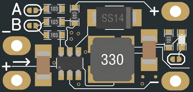
The Step Up Module 5V/8V/9V/12V 1.5A is a DC-DC boost converter designed to increase a lower input voltage (e.g., 5V) to a higher, selectable output voltage (e.g., 8V, 9V, or 12V). This module is ideal for applications where a stable, higher voltage is required from a lower voltage source, such as USB power supplies, batteries, or solar panels. It is compact, efficient, and capable of delivering up to 1.5A of output current.

Explore Projects Built with Step Up Module 5V/8V/9V/12V 1.5A

Use Cirkit Designer to design, explore, and prototype these projects online. Some projects support real-time simulation. Click "Open Project" to start designing instantly!
Battery-Powered DC-DC Converter System for Multi-Voltage Power Distribution
Image of test 1 ih: A project utilizing Step Up Module 5V/8V/9V/12V 1.5A in a practical application
This circuit converts a 38.5V battery output to multiple lower voltage levels using a series of DC-DC converters and a power module. It includes an emergency stop switch for safety and distributes power to various components such as a relay module, USB ports, and a bus servo adaptor.
Cirkit Designer LogoOpen Project in Cirkit Designer
12V UPS System with Dual 18650 Li-ion Battery Backup and Voltage Regulation
Image of Power supply: A project utilizing Step Up Module 5V/8V/9V/12V 1.5A in a practical application
This circuit is designed to provide an uninterruptible power supply (UPS) system with a 12V DC output. It includes a 12V 5A power supply connected to an AC source through a toggle switch, which charges a pair of 18650 Li-ion batteries via a voltage regulator (XL4016). The UPS module ensures a continuous power supply to the load by switching between the power supply and the battery bank.
Cirkit Designer LogoOpen Project in Cirkit Designer
Battery-Powered 18650 Li-ion Charger with USB Output and Adjustable Voltage Regulator
Image of Breadboard: A project utilizing Step Up Module 5V/8V/9V/12V 1.5A in a practical application
This circuit is a battery management and power supply system that uses three 3.7V batteries connected to a 3S 10A Li-ion 18650 Charger Protection Board Module for balanced charging and protection. The system includes a TP4056 Battery Charging Protection Module for additional charging safety, a Step Up Boost Power Converter to regulate and boost the voltage, and a USB regulator to provide a stable 5V output, controlled by a push switch.
Cirkit Designer LogoOpen Project in Cirkit Designer
Voltage Regulation System with MT3608 Boost and LM2596 Buck Converters
Image of solar system router ups: A project utilizing Step Up Module 5V/8V/9V/12V 1.5A in a practical application
This circuit consists of two MT3608 boost converters and an LM2596 step-down module, each connected to separate 12V power supplies. The MT3608 modules are configured to step up the voltage from their respective power supplies, while the LM2596 module steps down the voltage from a 12V battery. Diodes are used to ensure correct current flow direction, potentially for protection or isolation between different parts of the circuit.
Cirkit Designer LogoOpen Project in Cirkit Designer

Explore Projects Built with Step Up Module 5V/8V/9V/12V 1.5A

Use Cirkit Designer to design, explore, and prototype these projects online. Some projects support real-time simulation. Click "Open Project" to start designing instantly!
Image of test 1 ih: A project utilizing Step Up Module 5V/8V/9V/12V 1.5A in a practical application
Battery-Powered DC-DC Converter System for Multi-Voltage Power Distribution
This circuit converts a 38.5V battery output to multiple lower voltage levels using a series of DC-DC converters and a power module. It includes an emergency stop switch for safety and distributes power to various components such as a relay module, USB ports, and a bus servo adaptor.
Cirkit Designer LogoOpen Project in Cirkit Designer
Image of Power supply: A project utilizing Step Up Module 5V/8V/9V/12V 1.5A in a practical application
12V UPS System with Dual 18650 Li-ion Battery Backup and Voltage Regulation
This circuit is designed to provide an uninterruptible power supply (UPS) system with a 12V DC output. It includes a 12V 5A power supply connected to an AC source through a toggle switch, which charges a pair of 18650 Li-ion batteries via a voltage regulator (XL4016). The UPS module ensures a continuous power supply to the load by switching between the power supply and the battery bank.
Cirkit Designer LogoOpen Project in Cirkit Designer
Image of Breadboard: A project utilizing Step Up Module 5V/8V/9V/12V 1.5A in a practical application
Battery-Powered 18650 Li-ion Charger with USB Output and Adjustable Voltage Regulator
This circuit is a battery management and power supply system that uses three 3.7V batteries connected to a 3S 10A Li-ion 18650 Charger Protection Board Module for balanced charging and protection. The system includes a TP4056 Battery Charging Protection Module for additional charging safety, a Step Up Boost Power Converter to regulate and boost the voltage, and a USB regulator to provide a stable 5V output, controlled by a push switch.
Cirkit Designer LogoOpen Project in Cirkit Designer
Image of solar system router ups: A project utilizing Step Up Module 5V/8V/9V/12V 1.5A in a practical application
Voltage Regulation System with MT3608 Boost and LM2596 Buck Converters
This circuit consists of two MT3608 boost converters and an LM2596 step-down module, each connected to separate 12V power supplies. The MT3608 modules are configured to step up the voltage from their respective power supplies, while the LM2596 module steps down the voltage from a 12V battery. Diodes are used to ensure correct current flow direction, potentially for protection or isolation between different parts of the circuit.
Cirkit Designer LogoOpen Project in Cirkit Designer

Common Applications

  • Powering devices that require higher voltage from a lower voltage source
  • Battery-powered projects
  • Portable electronics
  • DIY electronics and prototyping
  • Arduino and microcontroller-based projects

Technical Specifications

Key Specifications

Parameter Value
Input Voltage Range 2.5V to 6V
Output Voltage Options 5V, 8V, 9V, 12V (selectable)
Maximum Output Current 1.5A
Efficiency Up to 92% (depending on load)
Dimensions ~36mm x 17mm x 14mm
Operating Temperature -40°C to +85°C

Pin Configuration and Descriptions

Pin Name Description
VIN Positive input voltage (2.5V to 6V)
GND Ground (common for input and output)
VOUT Positive output voltage (5V, 8V, 9V, or 12V)
SEL Voltage selection pin (used to set output voltage)

Usage Instructions

How to Use the Step Up Module

  1. Connect the Input Voltage:

    • Connect the positive terminal of your power source to the VIN pin.
    • Connect the negative terminal of your power source to the GND pin.
    • Ensure the input voltage is within the range of 2.5V to 6V.
  2. Set the Output Voltage:

    • Use the SEL pin to configure the desired output voltage. This is typically done by connecting the SEL pin to a specific voltage level or using a jumper (refer to the module's datasheet for exact configuration).
  3. Connect the Load:

    • Connect the positive terminal of your load to the VOUT pin.
    • Connect the negative terminal of your load to the GND pin.
  4. Power On:

    • Turn on the power source. The module will boost the input voltage to the selected output voltage.

Important Considerations

  • Input Voltage Range: Ensure the input voltage does not exceed 6V to avoid damaging the module.
  • Output Current: Do not exceed the maximum output current of 1.5A to prevent overheating or failure.
  • Heat Dissipation: For high current loads, consider adding a heatsink or ensuring proper ventilation to maintain efficiency and prevent overheating.
  • Voltage Selection: Double-check the output voltage setting before connecting sensitive devices to avoid damage.

Example: Using with an Arduino UNO

The Step Up Module can be used to power an Arduino UNO from a 3.7V Li-ion battery by boosting the voltage to 5V. Below is an example of how to connect the module:

  1. Connect the battery's positive terminal to the VIN pin and the negative terminal to the GND pin.
  2. Set the output voltage to 5V using the SEL pin.
  3. Connect the VOUT pin to the Arduino's 5V pin and the GND pin to the Arduino's GND pin.

Here is a simple Arduino sketch to blink an LED while powered by the Step Up Module:

// Simple LED Blink Example
// This code blinks an LED connected to pin 13 of the Arduino UNO.
// Ensure the Step Up Module is providing a stable 5V to the Arduino.

void setup() {
  pinMode(13, OUTPUT); // Set pin 13 as an output pin
}

void loop() {
  digitalWrite(13, HIGH); // Turn the LED on
  delay(1000);            // Wait for 1 second
  digitalWrite(13, LOW);  // Turn the LED off
  delay(1000);            // Wait for 1 second
}

Troubleshooting and FAQs

Common Issues and Solutions

Issue Possible Cause Solution
No output voltage Incorrect input voltage Ensure input voltage is within 2.5V-6V.
Output voltage is unstable Load exceeds maximum current rating Reduce the load to below 1.5A.
Module overheats High current draw or poor ventilation Add a heatsink or improve airflow.
Incorrect output voltage SEL pin not configured properly Verify and adjust the SEL pin settings.

FAQs

  1. Can I use this module with a 3.7V Li-ion battery?

    • Yes, the module can boost 3.7V to 5V, 8V, 9V, or 12V, depending on your configuration.
  2. What happens if I exceed the maximum input voltage?

    • Exceeding 6V on the input can damage the module. Always stay within the specified range.
  3. Can I use this module to power a Raspberry Pi?

    • While the module can provide 5V, ensure the current demand of the Raspberry Pi (and peripherals) does not exceed 1.5A.
  4. How do I select the output voltage?

    • Refer to the module's datasheet for specific instructions on configuring the SEL pin to set the desired output voltage.

By following this documentation, you can effectively use the Step Up Module 5V/8V/9V/12V 1.5A in your projects.