How to Use ESP32: Examples, Pinouts, and Specs
Introduction
The ESP32 is a powerful, low-cost microcontroller developed by Espressif Systems. It features integrated Wi-Fi and Bluetooth capabilities, making it an ideal choice for Internet of Things (IoT) applications, smart devices, and embedded systems. With its dual-core processor, extensive GPIO options, and support for various communication protocols, the ESP32 is a versatile solution for both hobbyists and professionals.
Explore Projects Built with ESP32


Explore Projects Built with ESP32
Common Applications and Use Cases
- IoT devices and smart home automation
- Wireless sensor networks
- Wearable technology
- Robotics and drones
- Industrial automation
- Real-time data monitoring and logging
Technical Specifications
The ESP32 is packed with features that make it suitable for a wide range of applications. Below are its key technical specifications:
General Specifications
- Processor: Dual-core Xtensa® 32-bit LX6 microprocessor
- Clock Speed: Up to 240 MHz
- RAM: 520 KB SRAM
- Flash Memory: Typically 4 MB (varies by module)
- Wi-Fi: 802.11 b/g/n (2.4 GHz)
- Bluetooth: v4.2 BR/EDR and BLE
- Operating Voltage: 3.0V to 3.6V
- GPIO Pins: Up to 34 configurable pins
- ADC Channels: 18 (12-bit resolution)
- DAC Channels: 2 (8-bit resolution)
- Communication Protocols: UART, SPI, I2C, I2S, CAN, PWM
- Power Consumption: Ultra-low power consumption in deep sleep mode (~10 µA)
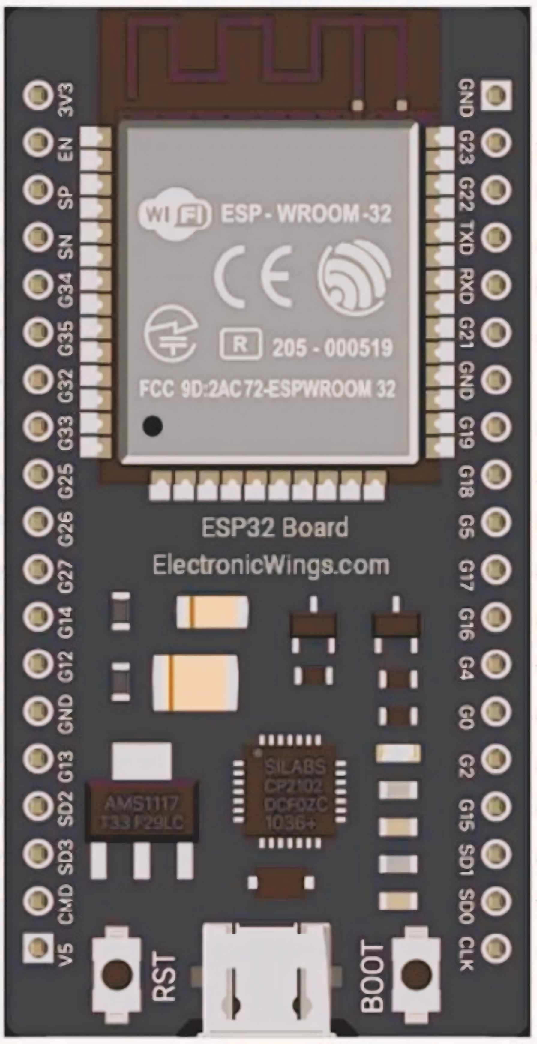
Pin Configuration and Descriptions
The ESP32 has multiple GPIO pins, each with specific functions. Below is a table summarizing the key pins and their descriptions:
| Pin | Function | Description |
|---|---|---|
| GPIO0 | Boot Mode Selection | Used to select boot mode during startup. |
| GPIO1 | UART TX | Transmit pin for UART communication. |
| GPIO3 | UART RX | Receive pin for UART communication. |
| GPIO12 | ADC2 Channel 5, Touch 5 | Can be used as an analog input or capacitive touch sensor. |
| GPIO13 | ADC2 Channel 4, Touch 4 | Can be used as an analog input or capacitive touch sensor. |
| GPIO21 | I2C SDA | Data line for I2C communication. |
| GPIO22 | I2C SCL | Clock line for I2C communication. |
| GPIO25 | DAC1, ADC2 Channel 8 | Can be used as a digital-to-analog converter or analog input. |
| GPIO26 | DAC2, ADC2 Channel 9 | Can be used as a digital-to-analog converter or analog input. |
| EN | Enable | Resets the chip when pulled low. |
| VIN | Power Input | Accepts input voltage (5V) for powering the ESP32. |
| GND | Ground | Ground connection. |
Note: Not all GPIO pins are available for general use, as some are reserved for internal functions. Refer to the ESP32 datasheet for detailed pin mappings.
Usage Instructions
How to Use the ESP32 in a Circuit
Powering the ESP32:
- The ESP32 can be powered via the VIN pin (5V) or through the micro-USB port (if available on the module). Ensure the input voltage is within the specified range (3.0V to 3.6V for direct power to the 3.3V pin).
Connecting Peripherals:
- Use the GPIO pins to connect sensors, actuators, or other peripherals. Configure the pins in your code as input or output as needed.
Programming the ESP32:
- The ESP32 can be programmed using the Arduino IDE, Espressif's ESP-IDF, or other compatible platforms. Install the necessary board support package (BSP) for the ESP32 in your development environment.
Uploading Code:
- Connect the ESP32 to your computer via USB. Select the correct board and port in your IDE, then upload your code.
Important Considerations and Best Practices
- Voltage Levels: The ESP32 operates at 3.3V logic levels. Avoid connecting 5V signals directly to its GPIO pins without a level shifter.
- Boot Mode: Ensure GPIO0 is not pulled high during boot to avoid entering flash mode unintentionally.
- Deep Sleep: Use deep sleep mode to significantly reduce power consumption in battery-powered applications.
- Wi-Fi and Bluetooth: Avoid using ADC2 channels when Wi-Fi is active, as they share resources and may cause conflicts.
Example Code for Arduino IDE
Below is an example of how to blink an LED connected to GPIO2 on the ESP32:
// Define the GPIO pin for the LED
#define LED_PIN 2

void setup() {
  // Set the LED pin as an output
  pinMode(LED_PIN, OUTPUT);
}

void loop() {
  // Turn the LED on
  digitalWrite(LED_PIN, HIGH);
  delay(1000); // Wait for 1 second

  // Turn the LED off
  digitalWrite(LED_PIN, LOW);
  delay(1000); // Wait for 1 second
}
Tip: Use the Serial Monitor in the Arduino IDE to debug your code and monitor outputs.
Troubleshooting and FAQs
Common Issues and Solutions
ESP32 Not Detected by Computer:
- Ensure the correct USB driver is installed (e.g., CP210x or CH340, depending on the module).
- Check the USB cable for data transfer capability (some cables are power-only).
Code Upload Fails:
- Press and hold the "BOOT" button on the ESP32 module while uploading the code.
- Verify the correct board and port are selected in the IDE.
Wi-Fi Connection Issues:
- Double-check the SSID and password in your code.
- Ensure the Wi-Fi network operates on the 2.4 GHz band (ESP32 does not support 5 GHz).
Random Resets or Instability:
- Check the power supply for sufficient current (at least 500 mA recommended).
- Add decoupling capacitors near the power pins to reduce noise.
FAQs
Q: Can the ESP32 be used with 5V sensors?
A: Yes, but you will need a level shifter to safely interface 5V signals with the ESP32's 3.3V logic.
Q: How do I update the ESP32 firmware?
A: Use the Espressif Flash Download Tool or the Arduino IDE to upload the latest firmware.
Q: Can I use both Wi-Fi and Bluetooth simultaneously?
A: Yes, the ESP32 supports simultaneous use of Wi-Fi and Bluetooth, but performance may vary depending on the application.
Q: What is the maximum range of the ESP32's Wi-Fi?
A: The range depends on environmental factors but typically extends up to 100 meters in open spaces.
By following this documentation, you can effectively utilize the ESP32 for your projects and troubleshoot common issues with ease.