How to Use 2.0TFTSPI ver1.3: Examples, Pinouts, and Specs
Introduction
The 2.0TFTSPI ver1.3 is a 2.0-inch TFT display module with an SPI interface, designed for seamless integration into microcontroller-based projects. It offers a high-resolution color output, making it ideal for applications requiring a compact yet vibrant display. This module is particularly suited for projects involving graphical user interfaces, data visualization, or real-time monitoring.
Explore Projects Built with 2.0TFTSPI ver1.3


Explore Projects Built with 2.0TFTSPI ver1.3
Common Applications and Use Cases
- Embedded systems requiring graphical displays
- IoT devices with user interfaces
- Portable devices and handheld instruments
- Real-time data visualization (e.g., temperature, humidity, or sensor data)
- Educational and prototyping projects with microcontrollers like Arduino or Raspberry Pi
Technical Specifications
Below are the key technical details of the 2.0TFTSPI ver1.3 module:
| Parameter | Specification |
|---|---|
| Display Type | TFT LCD |
| Screen Size | 2.0 inches |
| Resolution | 240 x 320 pixels |
| Interface | SPI (Serial Peripheral Interface) |
| Operating Voltage | 3.3V |
| Backlight Voltage | 3.0V to 3.3V |
| Current Consumption | ~50mA (typical) |
| Driver IC | ILI9341 |
| Viewing Angle | 160° |
| Operating Temperature | -20°C to 70°C |
| Dimensions | 42mm x 60mm x 4mm |
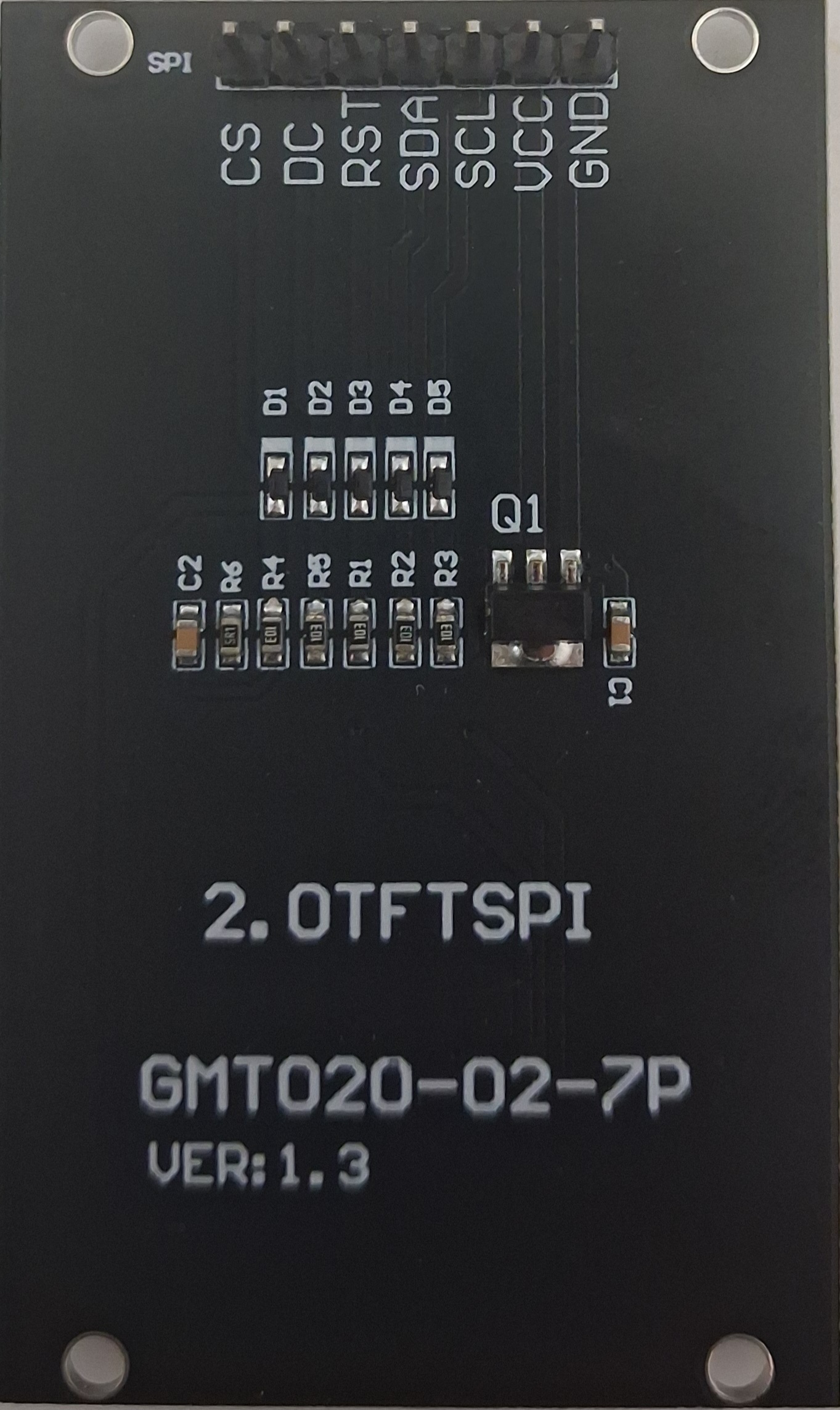
Pin Configuration and Descriptions
The 2.0TFTSPI ver1.3 module has a 7-pin interface. Below is the pinout description:
| Pin | Name | Description |
|---|---|---|
| 1 | GND | Ground connection |
| 2 | VCC | Power supply (3.3V) |
| 3 | SCL | SPI Clock (SCK) |
| 4 | SDA | SPI Data Input (MOSI) |
| 5 | RES | Reset pin (active low) |
| 6 | DC | Data/Command control pin (High = Data, Low = Command) |
| 7 | CS | Chip Select (active low) |
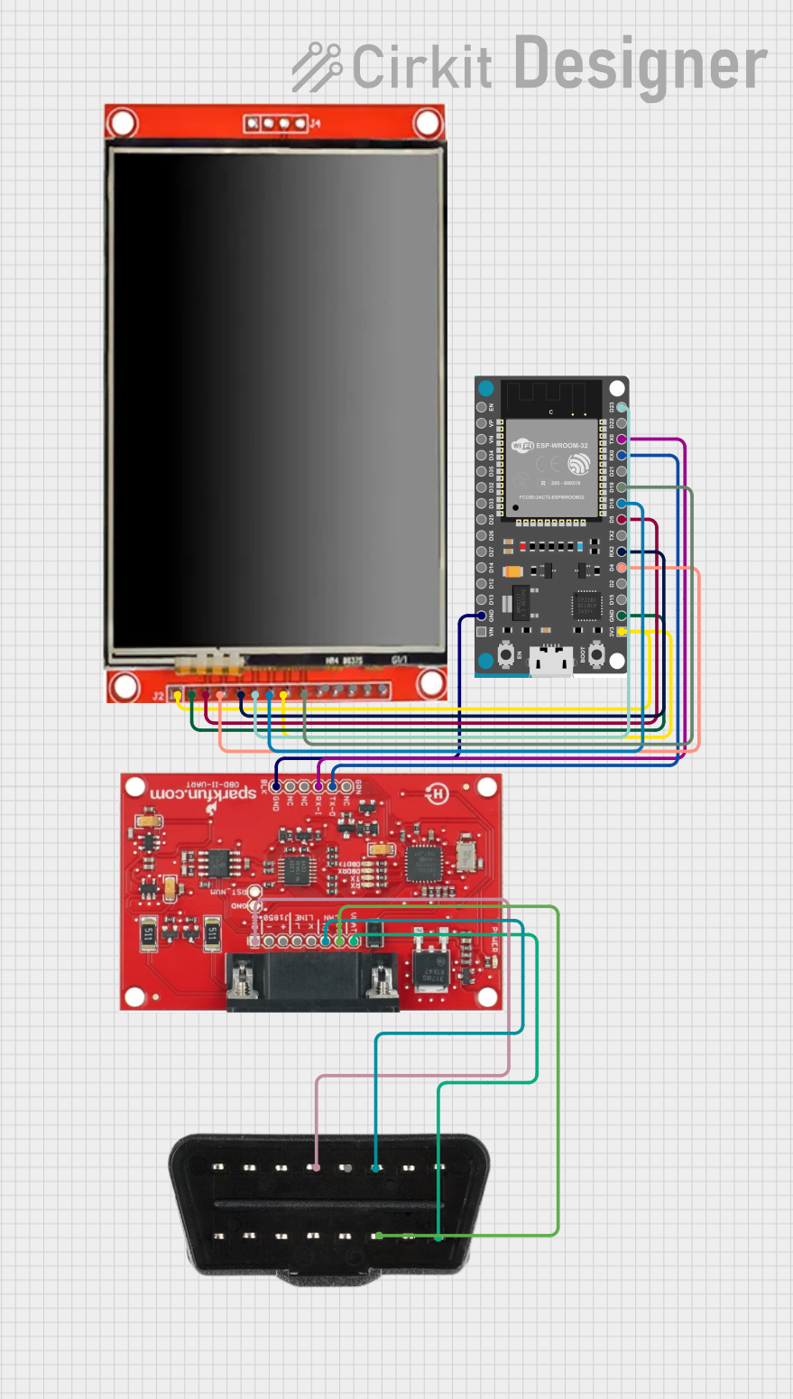
Usage Instructions
How to Use the Component in a Circuit
- Power Supply: Connect the
VCCpin to a 3.3V power source and theGNDpin to ground. - SPI Communication: Connect the
SCL(SPI Clock) andSDA(SPI Data Input) pins to the corresponding SPI pins on your microcontroller. - Control Pins:
- Connect the
RESpin to a GPIO pin on your microcontroller for resetting the display. - Use the
DCpin to toggle between data and command modes. - Connect the
CSpin to a GPIO pin to enable or disable the display module.
- Connect the
- Backlight: The backlight is powered through the
VCCpin. Ensure the voltage is within the specified range (3.0V to 3.3V).
Important Considerations and Best Practices
- Voltage Levels: Ensure all signal lines operate at 3.3V logic levels. If using a 5V microcontroller (e.g., Arduino UNO), use level shifters to avoid damaging the display.
- SPI Speed: Configure the SPI clock speed to a value supported by the display (typically up to 10 MHz for reliable operation).
- Initialization: Properly initialize the display using the ILI9341 driver commands before sending data.
- ESD Protection: Handle the module carefully to avoid electrostatic discharge, which can damage the sensitive components.
Example Code for Arduino UNO
Below is an example of how to use the 2.0TFTSPI ver1.3 with an Arduino UNO. This code uses the popular Adafruit_GFX and Adafruit_ILI9341 libraries.
#include <Adafruit_GFX.h>      // Graphics library for displays
#include <Adafruit_ILI9341.h>  // Driver library for ILI9341

// Define pin connections
#define TFT_CS   10  // Chip Select pin
#define TFT_DC    9  // Data/Command pin
#define TFT_RST   8  // Reset pin

// Create an instance of the display
Adafruit_ILI9341 tft = Adafruit_ILI9341(TFT_CS, TFT_DC, TFT_RST);

void setup() {
  // Initialize serial communication for debugging
  Serial.begin(9600);
  Serial.println("Initializing display...");

  // Initialize the TFT display
  tft.begin();
  tft.setRotation(1);  // Set display orientation (1 = landscape)

  // Fill the screen with a color
  tft.fillScreen(ILI9341_BLUE);

  // Display some text
  tft.setTextColor(ILI9341_WHITE);
  tft.setTextSize(2);
  tft.setCursor(10, 10);
  tft.println("Hello, TFT!");
}

void loop() {
  // Add your main code here
}
Note: Install the Adafruit_GFX and Adafruit_ILI9341 libraries via the Arduino Library Manager before running the code.
Troubleshooting and FAQs
Common Issues and Solutions
Display Not Turning On:
- Verify the power supply voltage (3.3V) and connections to the
VCCandGNDpins. - Check the
CS,DC, andRESpin connections to ensure proper control signals.
- Verify the power supply voltage (3.3V) and connections to the
No Output or Garbled Display:
- Ensure the SPI connections (
SCLandSDA) are correctly wired to the microcontroller. - Verify that the SPI clock speed is within the supported range (up to 10 MHz).
- Confirm that the display is initialized correctly using the ILI9341 driver commands.
- Ensure the SPI connections (
Backlight Not Working:
- Check the voltage supplied to the
VCCpin (should be between 3.0V and 3.3V). - Inspect the module for any physical damage to the backlight circuitry.
- Check the voltage supplied to the
Flickering or Unstable Display:
- Ensure stable power supply and proper grounding.
- Use decoupling capacitors near the power pins to reduce noise.
FAQs
Q1: Can I use this display with a 5V microcontroller?
A1: Yes, but you must use level shifters to convert the 5V logic signals to 3.3V to avoid damaging the display.
Q2: What is the maximum SPI clock speed supported?
A2: The display typically supports SPI clock speeds up to 10 MHz for reliable operation.
Q3: Can I use this display in outdoor applications?
A3: While the display operates in a wide temperature range (-20°C to 70°C), it is not sunlight-readable and may require additional protection against environmental factors.
Q4: Is there a library for easier integration?
A4: Yes, the Adafruit_GFX and Adafruit_ILI9341 libraries provide an easy-to-use interface for this display.
By following this documentation, you can effectively integrate the 2.0TFTSPI ver1.3 module into your projects and troubleshoot common issues.