How to Use Ks0008 Joystick Module: Examples, Pinouts, and Specs
Introduction
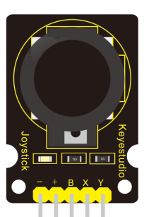
The Keyestudio Ks0008 Joystick Module is an analog input device designed for intuitive control in various applications. It features two axes of movement (X and Y) for directional control and includes a push-button for additional functionality. This module is widely used in robotics, gaming, and other interactive projects where precise control is required. Its compact design and ease of integration make it a popular choice for hobbyists and professionals alike.
Explore Projects Built with Ks0008 Joystick Module


Explore Projects Built with Ks0008 Joystick Module
Common Applications
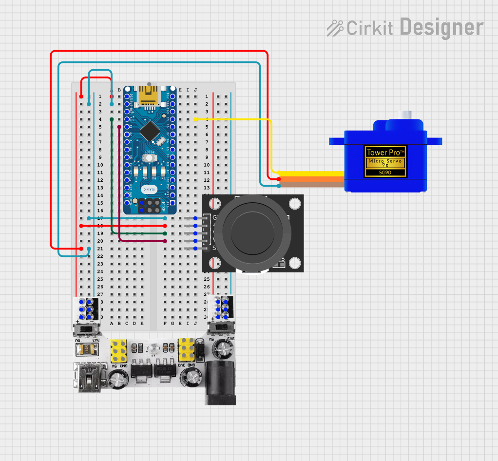
- Robotics: Controlling motors, servos, or robotic arms.
- Gaming: Custom game controllers or arcade-style input devices.
- DIY Projects: Interactive systems requiring directional input.
- Prototyping: Testing and developing user input systems.
Technical Specifications
The following table outlines the key technical details of the Ks0008 Joystick Module:
| Parameter | Specification |
|---|---|
| Manufacturer | Keyestudio |
| Part ID | Ks0008 |
| Operating Voltage | 5V |
| Output Type | Analog (X and Y axes), Digital (SW) |
| X-Axis Range | 0V to 5V |
| Y-Axis Range | 0V to 5V |
| Button Type | Momentary push-button (active low) |
| Dimensions | 34mm x 26mm x 32mm |
Pin Configuration
The Ks0008 Joystick Module has a 5-pin interface. The table below describes each pin:
| Pin | Label | Description |
|---|---|---|
| 1 | GND | Ground connection |
| 2 | +5V | Power supply (5V) |
| 3 | VRx | Analog output for X-axis movement |
| 4 | VRy | Analog output for Y-axis movement |
| 5 | SW | Digital output for the push-button (active low) |
Usage Instructions
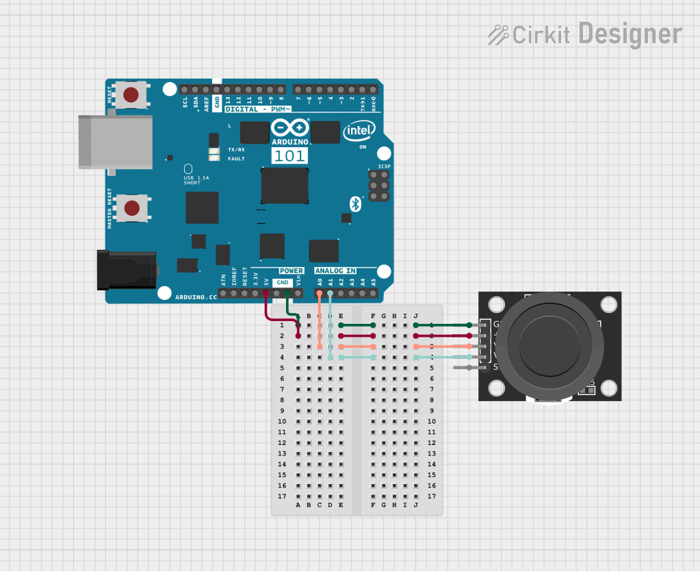
Connecting the Ks0008 Joystick Module
To use the Ks0008 Joystick Module in a circuit, follow these steps:
- Power the Module: Connect the
+5Vpin to the 5V output of your microcontroller and theGNDpin to ground. - Read Analog Outputs: Connect the
VRxandVRypins to the analog input pins of your microcontroller to read the X and Y axis values. - Read the Button State: Connect the
SWpin to a digital input pin to detect button presses.
Important Considerations
- Voltage Levels: Ensure the module is powered with 5V. Using higher voltages may damage the module.
- Debouncing the Button: If the push-button is used, consider implementing software debouncing to avoid false triggers.
- Calibration: The joystick may not return exact mid-point values when centered. Implement software calibration if precise centering is required.
Example: Using the Ks0008 with Arduino UNO
Below is an example Arduino sketch to read the joystick's X and Y axes and detect button presses:
// Define pin connections for the joystick module
const int VRxPin = A0; // X-axis connected to analog pin A0
const int VRyPin = A1; // Y-axis connected to analog pin A1
const int SWPin = 2;   // Push-button connected to digital pin 2

void setup() {
  // Initialize serial communication for debugging
  Serial.begin(9600);

  // Configure the push-button pin as input with pull-up resistor
  pinMode(SWPin, INPUT_PULLUP);
}

void loop() {
  // Read the X and Y axis values (0 to 1023)
  int xValue = analogRead(VRxPin);
  int yValue = analogRead(VRyPin);

  // Read the button state (LOW when pressed, HIGH when not pressed)
  int buttonState = digitalRead(SWPin);

  // Print the joystick values to the Serial Monitor
  Serial.print("X: ");
  Serial.print(xValue);
  Serial.print(" | Y: ");
  Serial.print(yValue);
  Serial.print(" | Button: ");
  Serial.println(buttonState == LOW ? "Pressed" : "Released");

  // Add a small delay for stability
  delay(100);
}
Notes:
- The
analogRead()function returns values between 0 and 1023, corresponding to 0V to 5V. - The button state is active low, meaning it reads
LOWwhen pressed andHIGHwhen released.
Troubleshooting and FAQs
Common Issues
No Output from the Joystick:
- Cause: Incorrect wiring or loose connections.
- Solution: Double-check all connections, ensuring the module is powered and properly connected to the microcontroller.
Inconsistent Axis Readings:
- Cause: Electrical noise or lack of calibration.
- Solution: Add capacitors (e.g., 0.1µF) between the analog output pins and ground to filter noise. Implement software calibration to account for variations.
Button Not Responding:
- Cause: Faulty button or incorrect pin configuration.
- Solution: Verify the
SWpin connection and ensure the pin is configured as an input with a pull-up resistor.
FAQs
Q: Can the Ks0008 Joystick Module be powered with 3.3V?
A: No, the module is designed to operate at 5V. Using 3.3V may result in unreliable performance or no output.
Q: How do I calibrate the joystick?
A: Read the X and Y axis values when the joystick is centered. Use these values as the mid-point in your code to adjust for any offset.
Q: Can I use the joystick for PWM motor control?
A: Yes, you can map the analog output values to PWM signals to control motor speed and direction.
Q: Is the push-button debounce necessary?
A: While not mandatory, debouncing ensures reliable button press detection, especially in noisy environments.