
How to Use LM2575 (TO263): Examples, Pinouts, and Specs
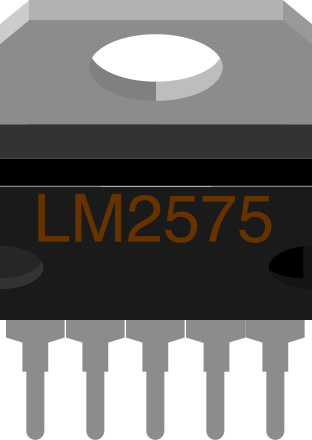
 Design with LM2575 (TO263) in Cirkit Designer
Introduction
The LM2575 is a step-down (buck) voltage regulator capable of delivering up to 1A of output current. It is designed for simplicity, efficiency, and reliability in power supply applications. With a wide input voltage range of 4V to 40V, the LM2575 is suitable for a variety of DC-DC conversion tasks. Its TO263 package offers a compact and thermally efficient solution, making it ideal for applications where space and heat dissipation are critical.
Explore Projects Built with LM2575 (TO263)
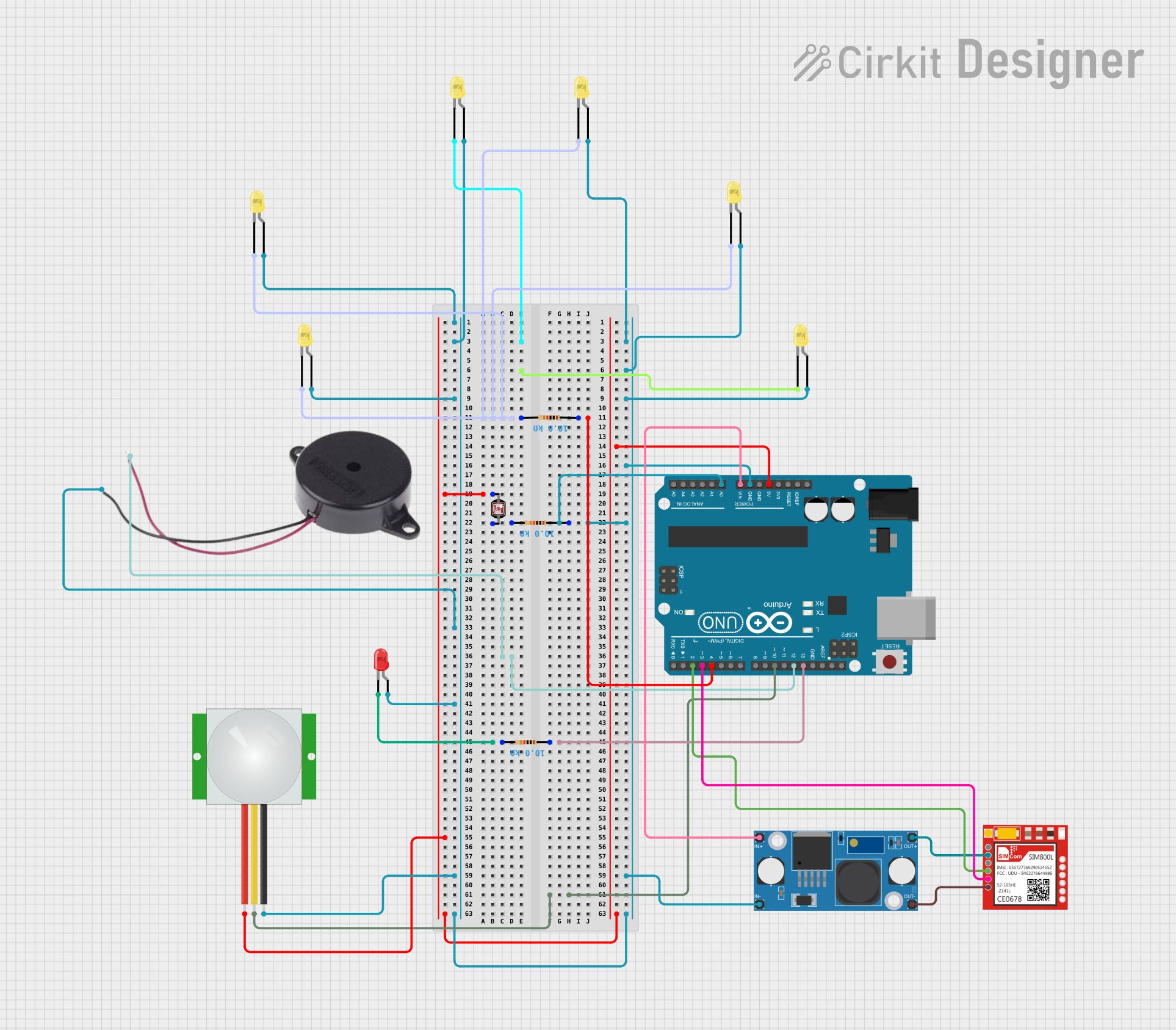 Open Project in Cirkit Designer
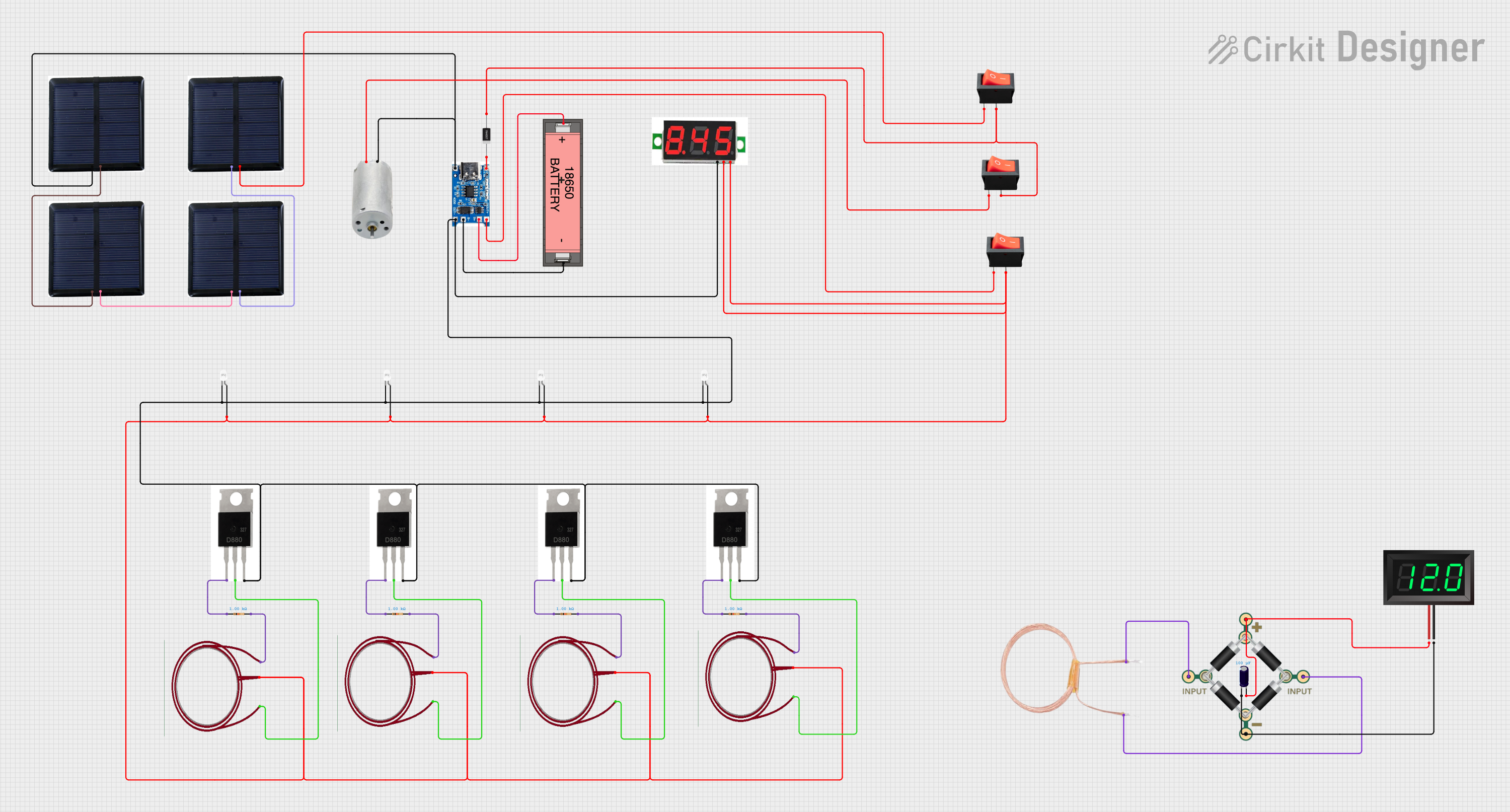 Open Project in Cirkit Designer
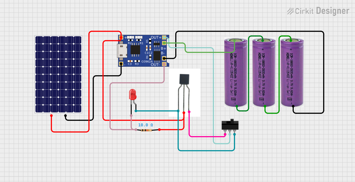 Open Project in Cirkit Designer
 Open Project in Cirkit Designer
Explore Projects Built with LM2575 (TO263)
Open Project in Cirkit DesignerOpen Project in Cirkit DesignerOpen Project in Cirkit DesignerOpen Project in Cirkit DesignerCommon Applications
- Battery-powered devices
- Industrial power supplies
- Automotive electronics
- Embedded systems
- Adjustable or fixed voltage regulators
Technical Specifications
Key Specifications
| Parameter | Value |
|---|---|
| Input Voltage Range | 4V to 40V |
| Output Voltage Options | 3.3V, 5V, 12V, 15V, Adjustable |
| Output Current | Up to 1A |
| Efficiency | Up to 88% |
| Switching Frequency | 52 kHz (fixed) |
| Operating Temperature Range | -40°C to +125°C |
| Package Type | TO263 |
Pin Configuration and Descriptions
The LM2575 in the TO263 package has 5 pins. Below is the pinout and description:
| Pin Number | Pin Name | Description |
|---|---|---|
| 1 | VIN | Input voltage pin. Connect to the unregulated DC input voltage. |
| 2 | Output | Regulated output voltage pin. Connect to the load. |
| 3 | Ground | Ground pin. Connect to the system ground. |
| 4 | Feedback | Feedback pin. Used to set the output voltage (for adjustable versions). |
| 5 | ON/OFF | Enable pin. Logic high enables the regulator; logic low disables it. |
Usage Instructions
How to Use the LM2575 in a Circuit
- Input Voltage: Ensure the input voltage is within the range of 4V to 40V. Use a decoupling capacitor (e.g., 100 µF) close to the VIN pin to reduce input noise.
- Output Voltage: For fixed-output versions, connect the output pin directly to the load. For adjustable versions, use a resistor divider network on the Feedback pin to set the desired output voltage.
- Inductor Selection: Choose an inductor with a current rating higher than 1A and a value recommended in the datasheet (typically 100 µH for most applications).
- Output Capacitor: Use a low-ESR capacitor (e.g., 330 µF) on the output pin to ensure stability and reduce ripple.
- ON/OFF Pin: If not used, connect the ON/OFF pin to VIN to enable the regulator.
Example Circuit
Below is a basic example of using the LM2575 to generate a 5V output from a 12V input:
Input Voltage (12V) ----+---- VIN (Pin 1)
                        |
                   [100 µF Capacitor]
                        |
                       GND

Output Voltage (5V) ----+---- Output (Pin 2)
                        |
                   [330 µF Capacitor]
                        |
                       GND

Feedback (Pin 4) -------+---- Resistor Divider (for adjustable version)
                        |
                       GND

ON/OFF (Pin 5) ---------+---- VIN (if always enabled)
                        |
                       GND
Arduino UNO Example Code
If using the LM2575 to power an Arduino UNO, connect the LM2575 output to the Arduino's 5V pin. Below is an example code to blink an LED:
// Blink an LED connected to pin 13 of the Arduino UNO
void setup() {
  pinMode(13, OUTPUT); // Set pin 13 as an output
}

void loop() {
  digitalWrite(13, HIGH); // Turn the LED on
  delay(1000);            // Wait for 1 second
  digitalWrite(13, LOW);  // Turn the LED off
  delay(1000);            // Wait for 1 second
}
Important Considerations
- Thermal Management: The TO263 package is designed for good thermal dissipation. Use a heatsink or ensure proper PCB layout with thermal vias if operating near maximum current.
- Ripple and Noise: Use low-ESR capacitors and proper PCB layout techniques to minimize output ripple and noise.
- Inductor Saturation: Ensure the inductor does not saturate at peak current.
Troubleshooting and FAQs
Common Issues and Solutions
Output Voltage is Incorrect
- Check the resistor divider network (for adjustable versions).
- Verify the input voltage is within the specified range.
- Ensure the feedback pin is properly connected.
Excessive Heat
- Ensure the load current does not exceed 1A.
- Check for proper thermal dissipation (e.g., heatsink or thermal vias).
High Output Ripple
- Use low-ESR capacitors on the output.
- Verify the inductor value and ensure it meets the recommended specifications.
Regulator Not Turning On
- Check the ON/OFF pin voltage. It should be logic high to enable the regulator.
- Verify all connections and ensure the input voltage is applied.
FAQs
Q: Can the LM2575 be used for negative voltage regulation?
A: No, the LM2575 is designed for positive voltage regulation. For negative voltages, consider using a different regulator designed for inverting applications.
Q: What happens if the input voltage exceeds 40V?
A: Exceeding the maximum input voltage can damage the regulator. Use a zener diode or TVS diode for input protection if voltage spikes are expected.
Q: Can I use the LM2575 without an inductor?
A: No, the inductor is a critical component for the buck converter operation. Omitting it will result in improper functionality.
By following these guidelines and best practices, the LM2575 can be effectively used in a wide range of power supply applications.