How to Use i2s mic module : Examples, Pinouts, and Specs
Introduction
The I2S microphone module is a digital microphone that utilizes the I2S (Inter-IC Sound) protocol for transmitting audio data. Unlike traditional analog microphones, which output analog signals requiring additional processing, the I2S microphone directly outputs digital audio data. This makes it ideal for applications requiring high-quality audio capture with minimal noise interference.
Explore Projects Built with i2s mic module
Explore Projects Built with i2s mic module
Common Applications and Use Cases
- Voice recognition systems (e.g., smart assistants)
- Audio recording and streaming
- Sound level monitoring
- IoT devices with audio input capabilities
- Noise-canceling systems
Technical Specifications
The following table outlines the key technical details of a typical I2S microphone module:
| Parameter | Value |
|---|---|
| Operating Voltage | 1.8V to 3.6V |
| Interface Protocol | I2S (Inter-IC Sound) |
| Sampling Rates | 8 kHz to 96 kHz |
| Signal-to-Noise Ratio | ~60 dB to 70 dB |
| Sensitivity | -26 dBFS ±3 dB |
| Power Consumption | ~1 mA (varies by model) |
| Output Format | 24-bit or 32-bit PCM |
| Operating Temperature | -40°C to +85°C |
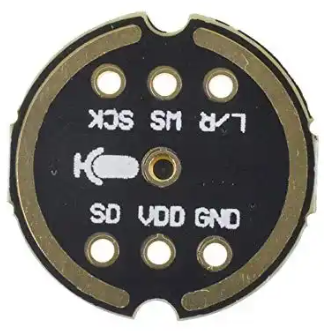
Pin Configuration and Descriptions
The I2S microphone module typically has the following pins:
| Pin Name | Description |
|---|---|
| VDD | Power supply pin (1.8V to 3.6V). Connect to a stable power source. |
| GND | Ground pin. Connect to the ground of the circuit. |
| WS (Word Select) | Determines the channel (left or right) for audio data. |
| SCK (Serial Clock) | Clock signal for synchronizing data transfer. |
| SD (Serial Data) | Outputs the digital audio data in I2S format. |
| L/R Select | Configures the microphone as left or right channel (optional, depending on model). |
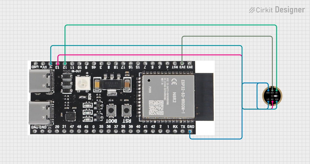
Usage Instructions
How to Use the I2S Mic Module in a Circuit
- Power the Module: Connect the
VDDpin to a 1.8V to 3.6V power source and theGNDpin to ground. - Connect I2S Lines:
- Connect the
SCKpin to the I2S clock line of your microcontroller. - Connect the
WSpin to the word select line of your microcontroller. - Connect the
SDpin to the I2S data input line of your microcontroller.
- Connect the
- Configure the Microcontroller:
- Set up the I2S peripheral on your microcontroller to match the microphone's sampling rate and data format.
- If the module has an
L/R Selectpin, configure it to determine whether the microphone outputs data for the left or right audio channel.
- Read Audio Data:
- Use the microcontroller's I2S interface to capture audio data from the
SDpin.
- Use the microcontroller's I2S interface to capture audio data from the
Important Considerations and Best Practices
- Power Supply: Ensure a stable and clean power supply to avoid noise in the audio signal.
- Clock Signal: The
SCKpin requires a stable clock signal. Verify that your microcontroller can generate the required clock frequency. - Sampling Rate: Match the sampling rate of the I2S microphone with the configuration of your microcontroller.
- PCB Layout: Minimize noise by keeping the I2S lines short and avoiding interference from other high-frequency signals.
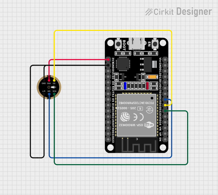
Example: Connecting to an Arduino UNO
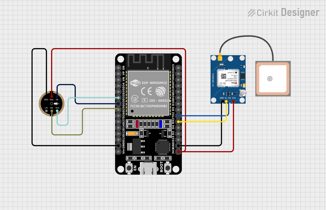
The Arduino UNO does not have a native I2S interface, but you can use an external I2S-compatible microcontroller (e.g., ESP32) to interface with the I2S microphone. Below is an example code snippet for an ESP32:
#include <driver/i2s.h>

// I2S configuration
#define I2S_NUM         I2S_NUM_0  // Use I2S port 0
#define I2S_WS_PIN      25         // Word Select pin
#define I2S_SCK_PIN     26         // Serial Clock pin
#define I2S_SD_PIN      22         // Serial Data pin

void setup() {
  // Configure I2S
  i2s_config_t i2s_config = {
    .mode = (i2s_mode_t)(I2S_MODE_MASTER | I2S_MODE_RX), // Master mode, receive data
    .sample_rate = 16000,                               // Sampling rate: 16 kHz
    .bits_per_sample = I2S_BITS_PER_SAMPLE_16BIT,       // 16-bit audio data
    .channel_format = I2S_CHANNEL_FMT_ONLY_LEFT,        // Left channel only
    .communication_format = I2S_COMM_FORMAT_I2S,       // I2S communication format
    .intr_alloc_flags = ESP_INTR_FLAG_LEVEL1,           // Interrupt level
    .dma_buf_count = 8,                                 // Number of DMA buffers
    .dma_buf_len = 64                                   // Length of each DMA buffer
  };

  // Install and configure I2S driver
  i2s_driver_install(I2S_NUM, &i2s_config, 0, NULL);

  // Configure I2S pins
  i2s_pin_config_t pin_config = {
    .bck_io_num = I2S_SCK_PIN,  // Serial Clock pin
    .ws_io_num = I2S_WS_PIN,    // Word Select pin
    .data_in_num = I2S_SD_PIN,  // Serial Data pin
    .data_out_num = I2S_PIN_NO_CHANGE // Not used
  };
  i2s_set_pin(I2S_NUM, &pin_config);
}

void loop() {
  // Buffer to store audio data
  uint8_t audio_data[1024];
  size_t bytes_read;

  // Read audio data from I2S
  i2s_read(I2S_NUM, audio_data, sizeof(audio_data), &bytes_read, portMAX_DELAY);

  // Process audio data (e.g., send to a server or save to storage)
}
Troubleshooting and FAQs
Common Issues and Solutions
No Audio Data Captured:
- Verify that the
SCK,WS, andSDpins are correctly connected to the microcontroller. - Ensure the I2S configuration (e.g., sampling rate, bit depth) matches the microphone's specifications.
- Verify that the
Distorted or Noisy Audio:
- Check the power supply for stability and noise.
- Ensure proper grounding of the circuit.
- Verify that the clock signal is stable and within the required frequency range.
Microphone Not Responding:
- Confirm that the
VDDpin is receiving the correct voltage. - Check for loose or incorrect connections.
- Confirm that the
FAQs
Q: Can I use the I2S microphone with a Raspberry Pi?
A: Yes, the Raspberry Pi has a native I2S interface that can be used to connect the I2S microphone. You will need to enable the I2S interface in the Raspberry Pi's configuration settings.
Q: What is the maximum distance between the microphone and the microcontroller?
A: To minimize signal degradation, keep the I2S lines as short as possible (typically less than 10 cm). For longer distances, consider using shielded cables.
Q: Can I use multiple I2S microphones in a single system?
A: Yes, you can use multiple I2S microphones by configuring each microphone to output data on a different channel (left or right) or by using separate I2S interfaces.