How to Use Mini traceur GPS 4G ZX908 CAT1 PCBA: Examples, Pinouts, and Specs
Introduction
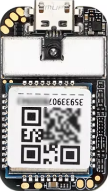
The Mini Traceur GPS 4G ZX908 CAT1 PCBA, manufactured by Shenzhen Bojietong Electronic Technology Co., Ltd, is a compact and versatile GPS tracking module. It supports 4G connectivity for real-time location tracking and monitoring. Designed with a printed circuit board assembly (PCBA), this module is easy to integrate into a wide range of applications, including vehicle tracking, asset monitoring, and IoT systems.
Explore Projects Built with Mini traceur GPS 4G ZX908 CAT1 PCBA


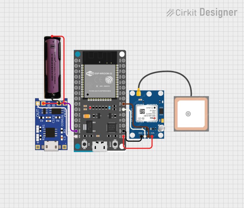
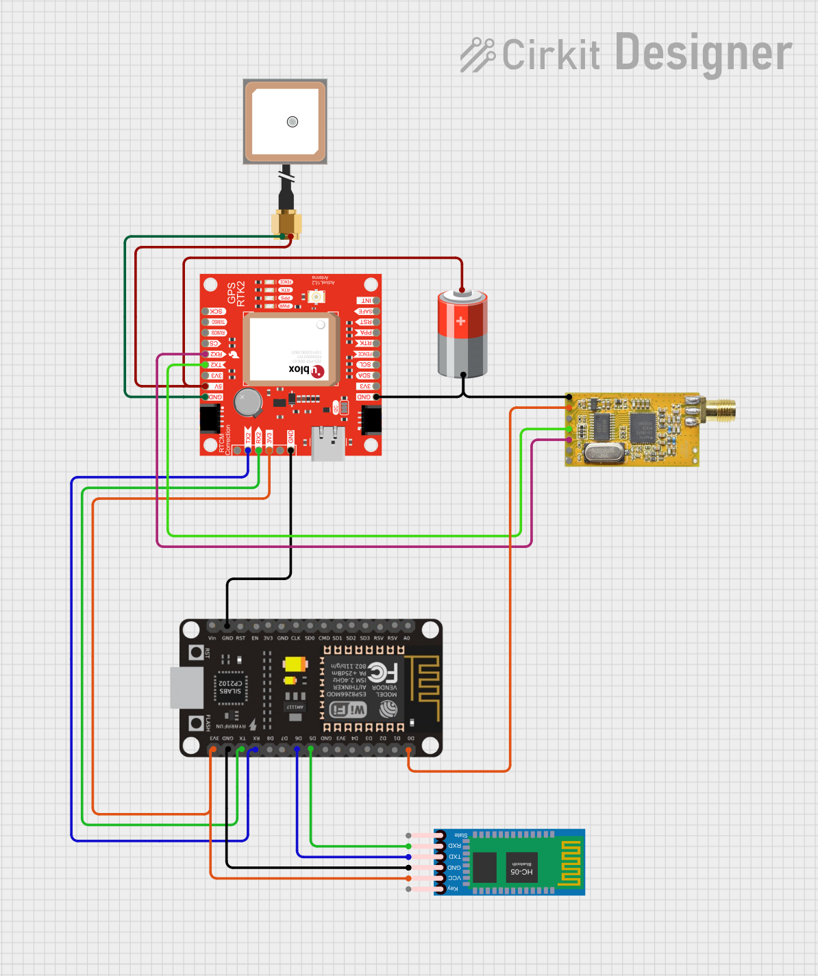
Explore Projects Built with Mini traceur GPS 4G ZX908 CAT1 PCBA
Common Applications and Use Cases
- Vehicle Tracking: Monitor the real-time location of cars, trucks, or fleets.
- Asset Monitoring: Track valuable assets in transit or storage.
- IoT Systems: Integrate into smart devices for location-based services.
- Personal Tracking: Use in wearable devices for personal safety and tracking.
- Logistics and Supply Chain: Ensure efficient tracking of goods and shipments.
Technical Specifications
Key Technical Details
| Parameter | Specification |
|---|---|
| Model | ZX908 CAT1 PCBA |
| Network Connectivity | 4G LTE (CAT1) |
| GPS Sensitivity | -165 dBm |
| Positioning Accuracy | < 2.5 meters |
| Operating Voltage | 3.3V to 4.2V |
| Power Consumption | < 1W (active mode) |
| Communication Protocols | UART, TCP/IP, MQTT |
| Operating Temperature | -40°C to +85°C |
| Dimensions | 40mm x 30mm x 5mm |
Pin Configuration and Descriptions
| Pin Number | Pin Name | Description |
|---|---|---|
| 1 | VCC | Power supply input (3.3V to 4.2V) |
| 2 | GND | Ground connection |
| 3 | TXD | UART Transmit Data |
| 4 | RXD | UART Receive Data |
| 5 | GPS_ANT | GPS antenna connection |
| 6 | NET_STATUS | Network status indicator (active high) |
| 7 | RESET | Module reset (active low) |
| 8 | PWR_KEY | Power on/off control |
Usage Instructions
How to Use the Component in a Circuit
- Power Supply: Connect the VCC pin to a stable power source (3.3V to 4.2V) and the GND pin to the ground.
- Antenna Connection: Attach a compatible GPS antenna to the GPS_ANT pin for optimal signal reception.
- UART Communication: Use the TXD and RXD pins to interface with a microcontroller or computer for data transmission and reception.
- Power Control: Use the PWR_KEY pin to turn the module on or off. Pull the pin low for at least 2 seconds to power on the module.
- Reset: If needed, pull the RESET pin low momentarily to reset the module.
Important Considerations and Best Practices
- Ensure the power supply is stable and within the specified voltage range to avoid damage to the module.
- Place the GPS antenna in an open area for better satellite signal reception.
- Use proper UART settings (e.g., baud rate) as specified in the module's datasheet.
- Avoid placing the module near high-frequency noise sources to prevent interference.
- For 4G connectivity, ensure a compatible SIM card is inserted and the network supports CAT1.
Example Code for Arduino UNO
Below is an example of how to interface the ZX908 module with an Arduino UNO for basic GPS data retrieval:
#include <SoftwareSerial.h>

// Define RX and TX pins for the ZX908 module
SoftwareSerial gpsSerial(10, 11); // RX = Pin 10, TX = Pin 11

void setup() {
  Serial.begin(9600); // Initialize Serial Monitor at 9600 baud
  gpsSerial.begin(9600); // Initialize GPS module communication at 9600 baud

  Serial.println("Initializing ZX908 GPS Module...");
}

void loop() {
  // Check if data is available from the GPS module
  if (gpsSerial.available()) {
    while (gpsSerial.available()) {
      char c = gpsSerial.read(); // Read one character at a time
      Serial.print(c); // Print the character to the Serial Monitor
    }
  }

  delay(1000); // Wait for 1 second before checking again
}
Note: Replace 10 and 11 with the appropriate pins if using different connections. Ensure the baud rate matches the module's default UART settings.
Troubleshooting and FAQs
Common Issues and Solutions
No GPS Signal:
- Cause: Poor antenna placement or interference.
- Solution: Place the antenna in an open area with a clear view of the sky. Avoid placing it near metal objects or electronic devices that may cause interference.
Module Not Powering On:
- Cause: Incorrect power supply or faulty connections.
- Solution: Verify the power supply voltage (3.3V to 4.2V) and check all connections.
No Data from UART:
- Cause: Incorrect UART settings or wiring.
- Solution: Ensure the TXD and RXD pins are correctly connected to the microcontroller. Verify the baud rate and other UART settings.
Network Connection Issues:
- Cause: Incompatible SIM card or poor network coverage.
- Solution: Use a SIM card that supports 4G LTE CAT1 and check network coverage in your area.
FAQs
Q: Can the module operate without a SIM card?
A: The GPS functionality can work without a SIM card, but 4G connectivity for data transmission requires a valid SIM card.Q: What is the default baud rate for UART communication?
A: The default baud rate is 9600 bps.Q: Can I use this module with a 5V microcontroller?
A: Yes, but you must use a level shifter to convert the 5V logic to 3.3V for the module's UART pins.Q: How do I check the network status?
A: Monitor the NET_STATUS pin. A high signal indicates an active network connection.
By following this documentation, users can effectively integrate and utilize the Mini Traceur GPS 4G ZX908 CAT1 PCBA in their projects.