How to Use Componente Tutorial de Servo: Examples, Pinouts, and Specs
Introduction
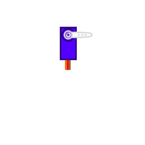
The Componente Tutorial de Servo is designed to help users understand and implement servo motors in electronic projects. Servo motors are widely used in robotics, automation, and control systems due to their precision and ease of use. This tutorial component simplifies the learning process by providing a comprehensive guide to the basics of servo motor operation, control methods, and practical applications.
Explore Projects Built with Componente Tutorial de Servo
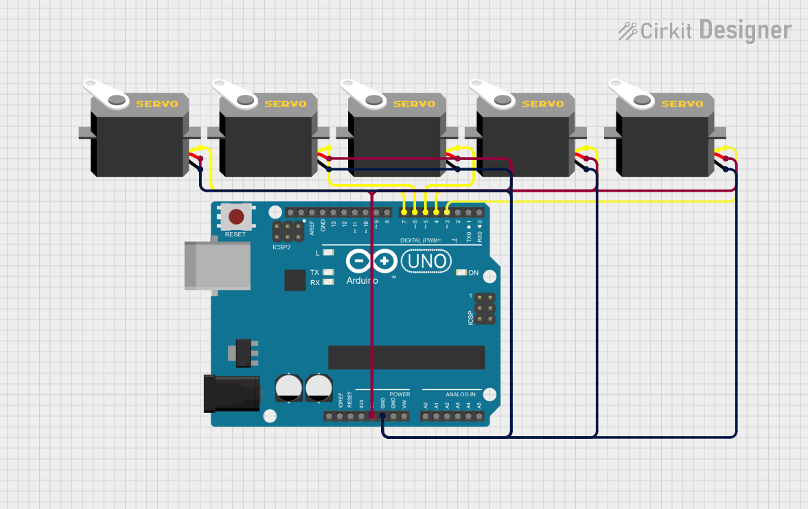
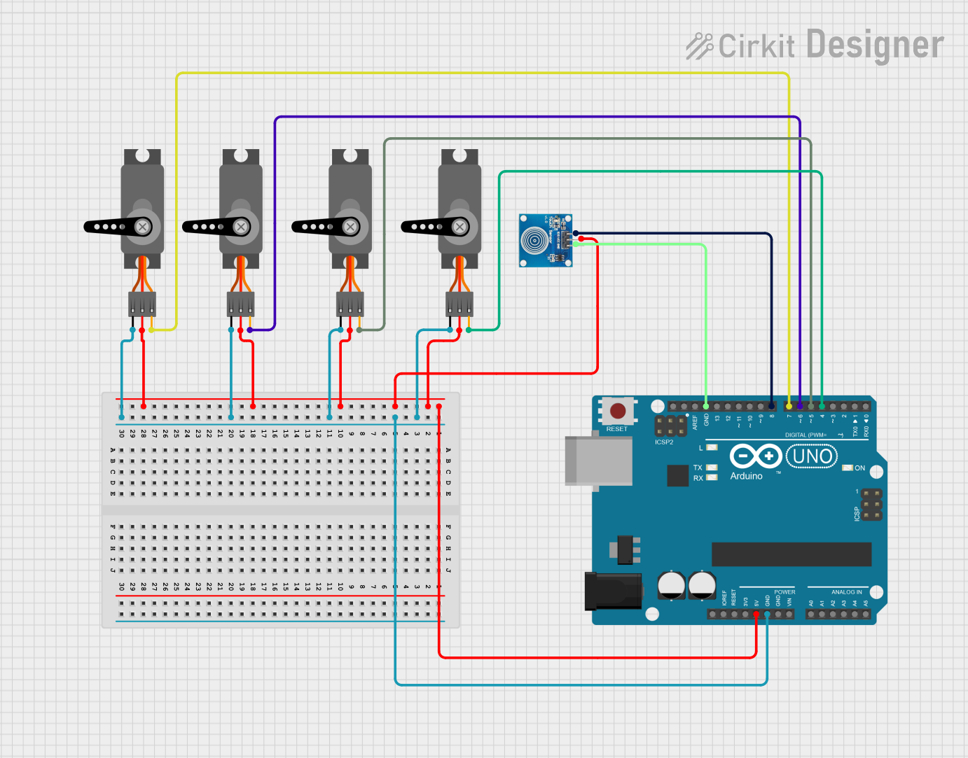
Explore Projects Built with Componente Tutorial de Servo
Common Applications and Use Cases
- Robotics: Controlling robotic arms, grippers, and joints.
- Automation: Positioning systems, such as camera gimbals or conveyor belts.
- Remote-Controlled Devices: Steering mechanisms in RC cars, planes, and boats.
- DIY Projects: Automated doors, pan-tilt camera mounts, and more.
Technical Specifications
Below are the general specifications for a standard servo motor, which this tutorial component is based on:
Key Technical Details
- Operating Voltage: 4.8V to 6V
- Operating Current: 100mA to 250mA (depending on load)
- Torque: 1.5 kg·cm to 10 kg·cm (varies by model)
- Rotation Range: Typically 0° to 180° (some models support 360° continuous rotation)
- Control Signal: Pulse Width Modulation (PWM)
- Pulse Width Range: 1ms to 2ms (1.5ms for neutral position)
- Connector Type: 3-pin (Signal, VCC, GND)
Pin Configuration and Descriptions
The servo motor typically has a 3-pin connector. Below is the pinout description:
| Pin Number | Name | Description |
|---|---|---|
| 1 | Signal | Receives PWM signal for position control. |
| 2 | VCC | Power supply (4.8V to 6V). |
| 3 | GND | Ground connection. |
Usage Instructions
How to Use the Component in a Circuit
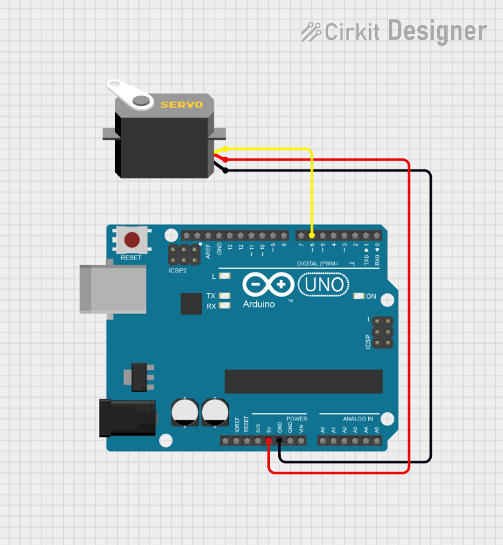
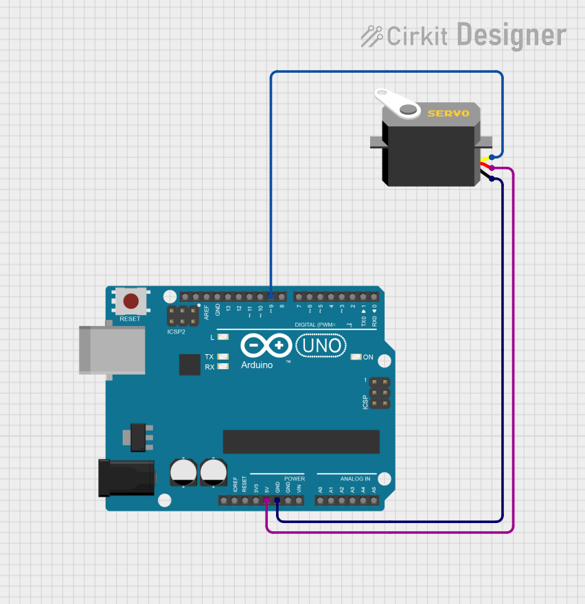
Connect the Servo Motor:
- Connect the Signal pin to a PWM-capable pin on your microcontroller (e.g., Arduino).
- Connect the VCC pin to a 5V power source.
- Connect the GND pin to the ground of your circuit.
Generate PWM Signal:
- Use a microcontroller to generate a PWM signal.
- Adjust the pulse width to control the servo's position:
- 1ms pulse: 0° position.
- 1.5ms pulse: Neutral (90°) position.
- 2ms pulse: 180° position.
Power Considerations:
- Use an external power source if the servo motor draws more current than your microcontroller can supply.
- Add a decoupling capacitor (e.g., 100µF) near the servo's power pins to stabilize the voltage.
Arduino UNO Example Code
Below is an example of how to control a servo motor using an Arduino UNO:
#include <Servo.h> // Include the Servo library

Servo myServo; // Create a Servo object

void setup() {
  myServo.attach(9); // Attach the servo to pin 9
}

void loop() {
  myServo.write(0); // Move servo to 0 degrees
  delay(1000);      // Wait for 1 second

  myServo.write(90); // Move servo to 90 degrees
  delay(1000);       // Wait for 1 second

  myServo.write(180); // Move servo to 180 degrees
  delay(1000);        // Wait for 1 second
}
Important Considerations and Best Practices
- Avoid stalling the servo motor, as it can overheat and damage the internal components.
- Use a separate power supply for multiple servos to prevent voltage drops.
- Ensure the PWM signal is stable and within the specified range to avoid erratic behavior.
Troubleshooting and FAQs
Common Issues and Solutions
Servo Motor Not Moving:
- Cause: Incorrect wiring or no PWM signal.
- Solution: Double-check the connections and ensure the signal pin is connected to a PWM-capable pin.
Servo Jitters or Erratic Movement:
- Cause: Unstable power supply or noisy PWM signal.
- Solution: Use a decoupling capacitor near the servo's power pins and ensure the PWM signal is clean.
Servo Overheating:
- Cause: Prolonged stalling or excessive load.
- Solution: Reduce the load or use a servo with higher torque.
Limited Range of Motion:
- Cause: Pulse width range not properly configured.
- Solution: Adjust the PWM signal to match the servo's specifications.
FAQs
Q: Can I control multiple servos with one Arduino?
- A: Yes, you can control multiple servos using the Servo library. However, ensure the power supply can handle the combined current draw.
Q: What happens if I exceed the servo's voltage rating?
- A: Exceeding the voltage rating can damage the servo motor. Always use a regulated power supply within the specified range.
Q: Can I use a servo motor for continuous rotation?
- A: Yes, but you need a servo modified for continuous rotation. In this case, the PWM signal controls speed and direction instead of position.
This concludes the documentation for the Componente Tutorial de Servo. Follow the guidelines and examples provided to successfully integrate servo motors into your projects!