Cirkit Designer Logo
Cirkit Designer
Your all-in-one circuit design IDE
Home / 
Component Documentation

How to Use 5v relay: Examples, Pinouts, and Specs

Image of 5v relay
Cirkit Designer LogoDesign with 5v relay in Cirkit Designer

Introduction

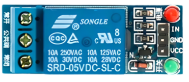
The Songle SRD-05VDC-SL-C is a 5V relay module that allows a low-power signal to control high-power devices, acting as an electrically operated switch. It uses an electromagnet to mechanically operate a switch, which can be used to turn on/off larger loads that a typical microcontroller cannot handle directly. Common applications include home automation, industrial controls, and automotive electronics where controlling lights, motors, and other high-power devices is required.

Explore Projects Built with 5v relay

Use Cirkit Designer to design, explore, and prototype these projects online. Some projects support real-time simulation. Click "Open Project" to start designing instantly!
ESP32 Wi-Fi Controlled Relay Switch
Image of nyoba: A project utilizing 5v relay in a practical application
This circuit uses an ESP32 microcontroller to control a 1-channel 5V relay. The ESP32 toggles the relay on and off every 5 seconds, allowing it to control an external device connected to the relay's output.
Cirkit Designer LogoOpen Project in Cirkit Designer
WeMos D1 R2 Controlled Relay Switching Circuit for AC Bulb and USB Charger
Image of Hand Gesture Light: A project utilizing 5v relay in a practical application
This circuit uses a WeMos D1 R2 microcontroller to control a 5V 2-relay module, which in turn controls the power to an AC bulb and a cellphone charger. The microcontroller also interfaces with a line tracking sensor, which likely provides input to control the relay states. The AC bulb and cellphone charger are powered by an AC wire connection, with the relay acting as a switch for the bulb.
Cirkit Designer LogoOpen Project in Cirkit Designer
Arduino UNO Controlled 5V Relay Switch
Image of relay: A project utilizing 5v relay in a practical application
This circuit uses an Arduino UNO to control a 5V relay. The relay is powered by the Arduino's Vin and GND pins, and its control input is connected to digital pin D9 on the Arduino. The provided code is a basic template with no specific functionality implemented.
Cirkit Designer LogoOpen Project in Cirkit Designer
Battery-Powered 4-Channel Relay Control with LED Indicators
Image of RELLAY BOARD TEST: A project utilizing 5v relay in a practical application
This circuit consists of a 5V battery powering a 4-channel relay module, which controls four LEDs (red, yellow, green, and blue) through individual resistors. Each relay channel is activated by a corresponding SPST toggle switch, allowing manual control of the LEDs.
Cirkit Designer LogoOpen Project in Cirkit Designer

Explore Projects Built with 5v relay

Use Cirkit Designer to design, explore, and prototype these projects online. Some projects support real-time simulation. Click "Open Project" to start designing instantly!
Image of nyoba: A project utilizing 5v relay in a practical application
ESP32 Wi-Fi Controlled Relay Switch
This circuit uses an ESP32 microcontroller to control a 1-channel 5V relay. The ESP32 toggles the relay on and off every 5 seconds, allowing it to control an external device connected to the relay's output.
Cirkit Designer LogoOpen Project in Cirkit Designer
Image of Hand Gesture Light: A project utilizing 5v relay in a practical application
WeMos D1 R2 Controlled Relay Switching Circuit for AC Bulb and USB Charger
This circuit uses a WeMos D1 R2 microcontroller to control a 5V 2-relay module, which in turn controls the power to an AC bulb and a cellphone charger. The microcontroller also interfaces with a line tracking sensor, which likely provides input to control the relay states. The AC bulb and cellphone charger are powered by an AC wire connection, with the relay acting as a switch for the bulb.
Cirkit Designer LogoOpen Project in Cirkit Designer
Image of relay: A project utilizing 5v relay in a practical application
Arduino UNO Controlled 5V Relay Switch
This circuit uses an Arduino UNO to control a 5V relay. The relay is powered by the Arduino's Vin and GND pins, and its control input is connected to digital pin D9 on the Arduino. The provided code is a basic template with no specific functionality implemented.
Cirkit Designer LogoOpen Project in Cirkit Designer
Image of RELLAY BOARD TEST: A project utilizing 5v relay in a practical application
Battery-Powered 4-Channel Relay Control with LED Indicators
This circuit consists of a 5V battery powering a 4-channel relay module, which controls four LEDs (red, yellow, green, and blue) through individual resistors. Each relay channel is activated by a corresponding SPST toggle switch, allowing manual control of the LEDs.
Cirkit Designer LogoOpen Project in Cirkit Designer

Technical Specifications

General Features

  • Operating Voltage: 5VDC
  • Switching Voltage: Up to 250VAC or 30VDC
  • Switching Current: Up to 10A (with proper heat dissipation)
  • Contact Type: SPDT (Single Pole Double Throw)
  • Coil Resistance: 70 Ohms ±10%
  • Operate Time: 10ms Max
  • Release Time: 5ms Max
  • Life Expectancy: 100,000 operations

Pin Configuration and Descriptions

Pin Number Pin Name Description
1 VCC Connects to 5V power supply
2 GND Connects to ground
3 IN Control signal input (active HIGH)
4 NO Normally Open contact; connects to load when relay is activated
5 COM Common contact; connects to power supply for load
6 NC Normally Closed contact; connected to load when relay is not activated
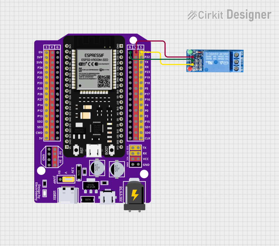
Usage Instructions

Connecting to a Circuit

  1. Power Connections:

    • Connect the VCC pin to a 5V power supply.
    • Connect the GND pin to the ground of the power supply.
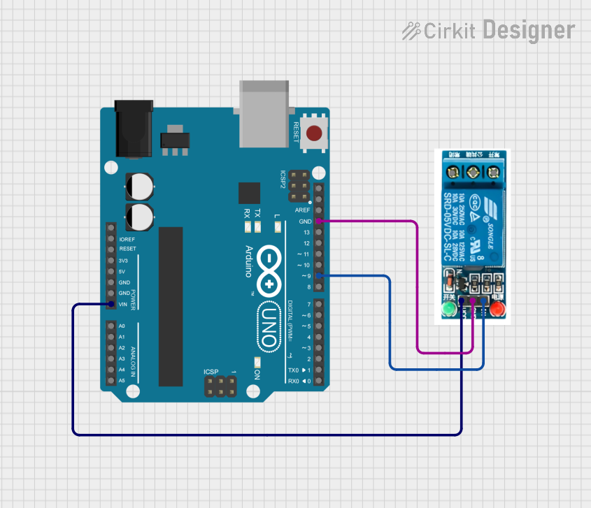
  2. Control Signal:

    • Connect the IN pin to a digital output pin of a microcontroller, such as an Arduino UNO.
  3. Load Connections:

    • Connect the COM pin to the power supply of the load you wish to control.
    • Connect either the NO or NC pin to the load, depending on whether you want the load to be powered when the relay is activated (NO) or when it is not activated (NC).

Best Practices

  • Use a flyback diode across the relay coil to prevent back EMF when the coil is de-energized.
  • Ensure the load does not exceed the rated current and voltage of the relay.
  • Consider using a relay driver circuit to protect the microcontroller from inductive spikes.
  • Use a proper heat sink if the current through the relay is close to the maximum rating.

Example Code for Arduino UNO

// Define the relay control pin
const int relayPin = 2;

void setup() {
  // Set the relay pin as an output
  pinMode(relayPin, OUTPUT);
}

void loop() {
  // Turn on the relay (NO contact is closed)
  digitalWrite(relayPin, HIGH);
  delay(1000); // Wait for 1 second
  
  // Turn off the relay (NO contact is open)
  digitalWrite(relayPin, LOW);
  delay(1000); // Wait for 1 second
}

Troubleshooting and FAQs

Common Issues

  • Relay does not switch: Check the power supply to the VCC and GND pins, and ensure the control signal is being sent to the IN pin.
  • Load does not power on: Verify the load is properly connected to the NO or NC and COM pins, and that the load's power supply is functioning.
  • Intermittent operation: Ensure that the relay's current and voltage ratings are not being exceeded, and check for loose connections.

FAQs

Q: Can I control this relay with a 3.3V signal? A: The relay is designed for a 5V signal, but it may operate at 3.3V. However, reliable operation is not guaranteed at lower voltages.

Q: How many relays can I control with an Arduino? A: It depends on the number of available digital output pins on your Arduino. Each relay requires one digital pin.

Q: Is it necessary to use a flyback diode? A: While the relay module may have built-in protection, it is good practice to use an external flyback diode, especially when switching inductive loads.

Q: Can I use PWM to control the relay? A: No, the relay requires a steady HIGH or LOW signal to switch states. PWM is not suitable for driving relays.

For further assistance, consult the manufacturer's datasheet and application notes.