Cirkit Designer Logo
Cirkit Designer
Your all-in-one circuit design IDE
Home / 
Component Documentation

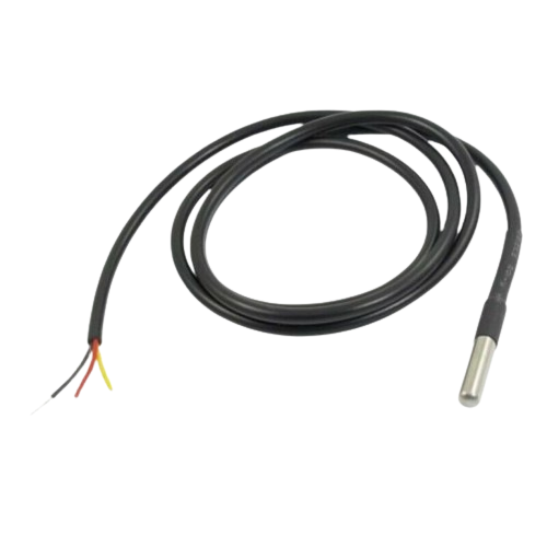
How to Use Temperature Sensor : Examples, Pinouts, and Specs

Image of Temperature Sensor
Cirkit Designer LogoDesign with Temperature Sensor in Cirkit Designer

Introduction

A temperature sensor is an electronic device designed to measure the temperature of its environment and convert this measurement into an electrical signal that can be interpreted by other devices, such as microcontrollers or analog-to-digital converters. These sensors are widely used in a variety of applications, including industrial control systems, consumer electronics, medical devices, and environmental monitoring.

Common applications include:

  • Monitoring and controlling temperature in HVAC systems.
  • Overheat protection in electronic appliances.
  • Temperature regulation in refrigeration and cooking appliances.
  • Environmental temperature monitoring in weather stations.
  • Body temperature measurement in medical devices.

Explore Projects Built with Temperature Sensor

Use Cirkit Designer to design, explore, and prototype these projects online. Some projects support real-time simulation. Click "Open Project" to start designing instantly!
Arduino UNO Based Temperature Monitoring System with DS18B20 Sensor
Image of DS18b20 sim test: A project utilizing Temperature Sensor  in a practical application
This circuit is designed to measure temperature using a DS18B20 sensor interfaced with an Arduino UNO. The Arduino reads temperature data from the sensor via a 1-Wire bus with a pull-up resistor and outputs the readings to the serial console.
Cirkit Designer LogoOpen Project in Cirkit Designer
Arduino UNO Based Temperature Monitoring with LM35 Sensor
Image of sattelite: A project utilizing Temperature Sensor  in a practical application
This circuit is designed to measure temperature using an LM35 temperature sensor and display the readings in degrees Celsius. The sensor's output voltage is read by an Arduino UNO's analog input, which then converts the voltage to a temperature value. The Arduino is programmed to serially output the temperature data, which can be monitored in real-time.
Cirkit Designer LogoOpen Project in Cirkit Designer
Arduino UNO Based LM35 Temperature Sensor Monitoring System
Image of Measuring Temperature With LM35 and Arduino UNO: A project utilizing Temperature Sensor  in a practical application
This circuit is designed to measure temperature using an LM35 temperature sensor interfaced with an Arduino UNO microcontroller. The sensor's output voltage, which is proportional to the temperature, is read by the Arduino's analog input A0. The embedded code on the Arduino processes this signal to calculate and output the temperature in both Celsius and Fahrenheit to the serial monitor.
Cirkit Designer LogoOpen Project in Cirkit Designer
Arduino UNO with DS18B20 Temperature Sensor Monitoring
Image of Measure Temperature With Arduino UNO and DS18B20: A project utilizing Temperature Sensor  in a practical application
This circuit is designed to measure temperature using a DS18B20 temperature sensor interfaced with an Arduino UNO microcontroller. The sensor's data line is connected to digital pin 4 of the Arduino through a 4.7k Ohm pull-up resistor, and the Arduino runs a sketch that reads the temperature in Celsius and Fahrenheit, then outputs the readings to the serial monitor. The purpose of the circuit is to provide a digital temperature reading for monitoring or control applications.
Cirkit Designer LogoOpen Project in Cirkit Designer

Explore Projects Built with Temperature Sensor

Use Cirkit Designer to design, explore, and prototype these projects online. Some projects support real-time simulation. Click "Open Project" to start designing instantly!
Image of DS18b20 sim test: A project utilizing Temperature Sensor  in a practical application
Arduino UNO Based Temperature Monitoring System with DS18B20 Sensor
This circuit is designed to measure temperature using a DS18B20 sensor interfaced with an Arduino UNO. The Arduino reads temperature data from the sensor via a 1-Wire bus with a pull-up resistor and outputs the readings to the serial console.
Cirkit Designer LogoOpen Project in Cirkit Designer
Image of sattelite: A project utilizing Temperature Sensor  in a practical application
Arduino UNO Based Temperature Monitoring with LM35 Sensor
This circuit is designed to measure temperature using an LM35 temperature sensor and display the readings in degrees Celsius. The sensor's output voltage is read by an Arduino UNO's analog input, which then converts the voltage to a temperature value. The Arduino is programmed to serially output the temperature data, which can be monitored in real-time.
Cirkit Designer LogoOpen Project in Cirkit Designer
Image of Measuring Temperature With LM35 and Arduino UNO: A project utilizing Temperature Sensor  in a practical application
Arduino UNO Based LM35 Temperature Sensor Monitoring System
This circuit is designed to measure temperature using an LM35 temperature sensor interfaced with an Arduino UNO microcontroller. The sensor's output voltage, which is proportional to the temperature, is read by the Arduino's analog input A0. The embedded code on the Arduino processes this signal to calculate and output the temperature in both Celsius and Fahrenheit to the serial monitor.
Cirkit Designer LogoOpen Project in Cirkit Designer
Image of Measure Temperature With Arduino UNO and DS18B20: A project utilizing Temperature Sensor  in a practical application
Arduino UNO with DS18B20 Temperature Sensor Monitoring
This circuit is designed to measure temperature using a DS18B20 temperature sensor interfaced with an Arduino UNO microcontroller. The sensor's data line is connected to digital pin 4 of the Arduino through a 4.7k Ohm pull-up resistor, and the Arduino runs a sketch that reads the temperature in Celsius and Fahrenheit, then outputs the readings to the serial monitor. The purpose of the circuit is to provide a digital temperature reading for monitoring or control applications.
Cirkit Designer LogoOpen Project in Cirkit Designer

Technical Specifications

Key Technical Details

  • Operating Voltage Range: Typically 3.3V to 5V.
  • Output Signal: Analog voltage or digital data (depending on the type of sensor).
  • Temperature Range: Varies by model (e.g., -55°C to +125°C).
  • Accuracy: Varies by model (e.g., ±0.5°C).
  • Response Time: Varies by model.

Pin Configuration and Descriptions

Pin Number Name Description
1 VCC Power supply input, typically 3.3V to 5V.
2 OUT Output signal, analog or digital.
3 GND Ground connection.

Usage Instructions

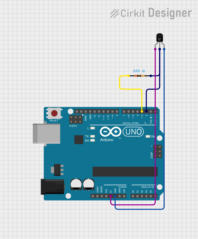
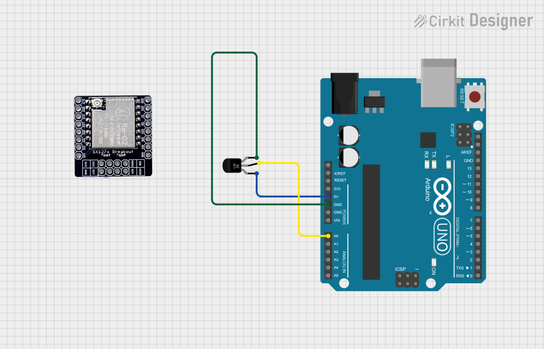
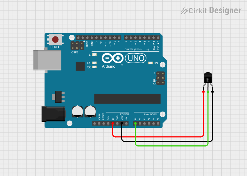
How to Use the Component in a Circuit

  1. Power Supply: Connect the VCC pin to a power source within the sensor's operating voltage range.
  2. Signal Output: Connect the OUT pin to an analog input on a microcontroller for analog sensors, or to a digital input for digital sensors.
  3. Ground Connection: Connect the GND pin to the ground of the power supply and microcontroller.

Important Considerations and Best Practices

  • Ensure that the sensor is placed in an appropriate location for accurate temperature readings, avoiding proximity to heat-generating components.
  • Use proper decoupling capacitors close to the sensor's power supply pin to minimize noise.
  • For analog sensors, calibrate the output signal to match the microcontroller's analog-to-digital converter (ADC) reference voltage.
  • For digital sensors, ensure that the communication protocol (e.g., I2C, SPI) is correctly implemented.

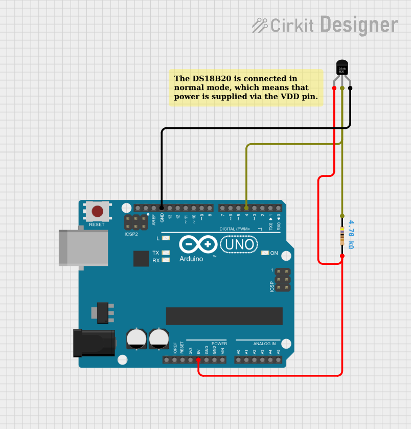
Example Code for Arduino UNO

// Include necessary libraries for digital sensors if required.
#include <OneWire.h>
#include <DallasTemperature.h>

// Data wire is connected to Arduino digital pin 2.
#define ONE_WIRE_BUS 2

// Setup a oneWire instance to communicate with the sensor.
OneWire oneWire(ONE_WIRE_BUS);

// Pass oneWire reference to DallasTemperature library.
DallasTemperature sensors(&oneWire);

void setup() {
  // Start serial communication for debugging.
  Serial.begin(9600);
  // Start the temperature sensor.
  sensors.begin();
}

void loop() {
  // Request temperature measurement.
  sensors.requestTemperatures();
  // Fetch and print the temperature in Celsius.
  Serial.print("Temperature: ");
  Serial.print(sensors.getTempCByIndex(0));
  Serial.println("°C");
  
  // Wait 1 second before next measurement.
  delay(1000);
}

Troubleshooting and FAQs

Common Issues

  • Inaccurate Readings: Ensure the sensor is not affected by external heat sources and that it's properly calibrated.
  • No Output Signal: Check the wiring and connections, and ensure the power supply is within the specified range.
  • Intermittent Signal: Verify that the sensor is not damaged and that there are no loose connections.

Solutions and Tips for Troubleshooting

  • Calibration: For analog sensors, use a known temperature reference to calibrate the output signal.
  • Wiring Check: Recheck all connections, including VCC, OUT, and GND, for any loose wires or soldering issues.
  • Power Supply: Use a multimeter to verify that the voltage at the VCC pin is stable and within the specified range.

FAQs

Q: Can I use the temperature sensor with a 3.3V system? A: Yes, most temperature sensors can operate at 3.3V, but always check the specific sensor's datasheet.

Q: How long does it take for the sensor to provide an accurate reading? A: This depends on the sensor's response time, which can be found in the datasheet. Typically, it ranges from a few milliseconds to seconds.

Q: Is it possible to use multiple temperature sensors on the same microcontroller? A: Yes, for digital sensors using protocols like I2C or OneWire, you can connect multiple sensors to the same data bus with unique addresses. For analog sensors, you will need multiple analog input pins.

Remember to consult the specific datasheet of the temperature sensor model you are using for precise information, as specifications can vary significantly between different models.