Cirkit Designer Logo
Cirkit Designer
Your all-in-one circuit design IDE
Home / 
Component Documentation

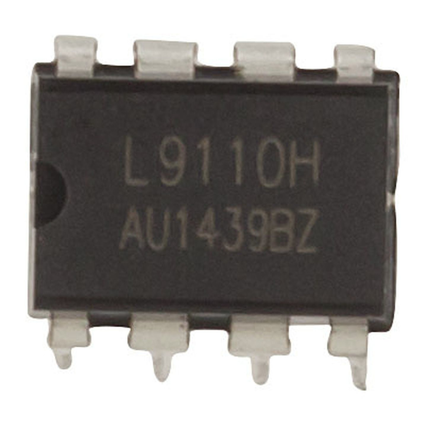
How to Use L9110 Bridge Motor Driver IC DIP 8: Examples, Pinouts, and Specs

Image of L9110 Bridge Motor Driver IC DIP 8
Cirkit Designer LogoDesign with L9110 Bridge Motor Driver IC DIP 8 in Cirkit Designer

Introduction

The L9110 is a dual H-bridge motor driver IC in a compact DIP-8 package. It is designed to control the direction and speed of DC motors, making it an essential component for motorized projects. The IC can drive two DC motors simultaneously, with independent control over each motor. Its small size and ease of use make it ideal for applications in robotics, automation, and other motor control systems.

Explore Projects Built with L9110 Bridge Motor Driver IC DIP 8

Use Cirkit Designer to design, explore, and prototype these projects online. Some projects support real-time simulation. Click "Open Project" to start designing instantly!
ESP32-Controlled Multi-Axis Actuator System with Orientation Sensing and Light Detection
Image of Auto_Level_Table: A project utilizing L9110 Bridge Motor Driver IC DIP 8 in a practical application
This circuit features an ESP32 S3 N32R8V microcontroller interfaced with multiple IBT-2 H-Bridge Motor Drivers to control several Linear Actuators, and it receives input from KY-018 LDR Photo Resistors and Pushbuttons. The ESP32 is powered by a 5V supply from an Adafruit MPM3610 5V Buck Converter, while the Linear Actuators and Motor Drivers are powered by a 12V 7Ah battery. Additionally, the ESP32 communicates with an Adafruit BNO085 9-DOF Orientation IMU Fusion Breakout for orientation sensing.
Cirkit Designer LogoOpen Project in Cirkit Designer
Raspberry Pi 4B Controlled Multi-Motor Driver System
Image of vend: A project utilizing L9110 Bridge Motor Driver IC DIP 8 in a practical application
This circuit is designed to control multiple DC motors using a Raspberry Pi 4B as the central processing unit and several L9110 motor driver ICs. The Raspberry Pi's GPIO pins are connected to the input pins of the L9110s to control the speed and direction of the connected motors. A 12V battery provides power to the motor drivers and the motors, with the Raspberry Pi managing the logic level control signals.
Cirkit Designer LogoOpen Project in Cirkit Designer
ESP32-Controlled 4-Wheel Robot with L293D Motor Drivers
Image of Truck Movement: A project utilizing L9110 Bridge Motor Driver IC DIP 8 in a practical application
This circuit is designed to control four 12V geared motors using two L293D motor driver ICs, which are interfaced with an ESP32 microcontroller. The ESP32 uses GPIO pins to send control signals to the L293D drivers, which then power the motors accordingly. The embedded code on the ESP32 defines functions for forward, backward, left, and right movements, indicating the circuit is likely part of a robotic vehicle control system.
Cirkit Designer LogoOpen Project in Cirkit Designer
ESP32-Based Multi-Sensor Robotic Controller with Dual L298N Motor Drivers
Image of drone : A project utilizing L9110 Bridge Motor Driver IC DIP 8 in a practical application
This circuit is designed for a robotics or autonomous vehicle application, utilizing an ESP32 microcontroller to interface with various sensors and control multiple DC motors through L298N motor drivers. It features capabilities for image processing, distance measurement, sound detection, and motion sensing, enabling complex environment interaction and navigation.
Cirkit Designer LogoOpen Project in Cirkit Designer

Explore Projects Built with L9110 Bridge Motor Driver IC DIP 8

Use Cirkit Designer to design, explore, and prototype these projects online. Some projects support real-time simulation. Click "Open Project" to start designing instantly!
Image of Auto_Level_Table: A project utilizing L9110 Bridge Motor Driver IC DIP 8 in a practical application
ESP32-Controlled Multi-Axis Actuator System with Orientation Sensing and Light Detection
This circuit features an ESP32 S3 N32R8V microcontroller interfaced with multiple IBT-2 H-Bridge Motor Drivers to control several Linear Actuators, and it receives input from KY-018 LDR Photo Resistors and Pushbuttons. The ESP32 is powered by a 5V supply from an Adafruit MPM3610 5V Buck Converter, while the Linear Actuators and Motor Drivers are powered by a 12V 7Ah battery. Additionally, the ESP32 communicates with an Adafruit BNO085 9-DOF Orientation IMU Fusion Breakout for orientation sensing.
Cirkit Designer LogoOpen Project in Cirkit Designer
Image of vend: A project utilizing L9110 Bridge Motor Driver IC DIP 8 in a practical application
Raspberry Pi 4B Controlled Multi-Motor Driver System
This circuit is designed to control multiple DC motors using a Raspberry Pi 4B as the central processing unit and several L9110 motor driver ICs. The Raspberry Pi's GPIO pins are connected to the input pins of the L9110s to control the speed and direction of the connected motors. A 12V battery provides power to the motor drivers and the motors, with the Raspberry Pi managing the logic level control signals.
Cirkit Designer LogoOpen Project in Cirkit Designer
Image of Truck Movement: A project utilizing L9110 Bridge Motor Driver IC DIP 8 in a practical application
ESP32-Controlled 4-Wheel Robot with L293D Motor Drivers
This circuit is designed to control four 12V geared motors using two L293D motor driver ICs, which are interfaced with an ESP32 microcontroller. The ESP32 uses GPIO pins to send control signals to the L293D drivers, which then power the motors accordingly. The embedded code on the ESP32 defines functions for forward, backward, left, and right movements, indicating the circuit is likely part of a robotic vehicle control system.
Cirkit Designer LogoOpen Project in Cirkit Designer
Image of drone : A project utilizing L9110 Bridge Motor Driver IC DIP 8 in a practical application
ESP32-Based Multi-Sensor Robotic Controller with Dual L298N Motor Drivers
This circuit is designed for a robotics or autonomous vehicle application, utilizing an ESP32 microcontroller to interface with various sensors and control multiple DC motors through L298N motor drivers. It features capabilities for image processing, distance measurement, sound detection, and motion sensing, enabling complex environment interaction and navigation.
Cirkit Designer LogoOpen Project in Cirkit Designer

Common Applications

  • Robotics (e.g., motorized wheels, robotic arms)
  • Automation systems
  • Small motorized toys
  • DIY electronics projects
  • Conveyor belt systems

Technical Specifications

The L9110 motor driver IC is designed for low-power motor control applications. Below are its key technical details:

Parameter Value
Operating Voltage 2.5V to 12V
Output Current (per channel) 800mA (continuous)
Peak Output Current 1.5A
Logic Input Voltage 0V to 5V
Number of Channels 2 (dual H-bridge)
Package Type DIP-8
Operating Temperature -40°C to +85°C

Pin Configuration and Descriptions

The L9110 IC has 8 pins, as described in the table below:

Pin Number Pin Name Description
1 A-1A Input signal for Motor A (controls direction)
2 A-1B Input signal for Motor A (controls direction)
3 GND Ground (0V reference)
4 VCC Power supply for the IC (2.5V to 12V)
5 B-1B Input signal for Motor B (controls direction)
6 B-1A Input signal for Motor B (controls direction)
7 Motor B+ Output terminal for Motor B
8 Motor A+ Output terminal for Motor A

Usage Instructions

The L9110 motor driver IC is straightforward to use in motor control circuits. Below are the steps and considerations for using it effectively:

Connecting the L9110 to a Circuit

  1. Power Supply: Connect the VCC pin (Pin 4) to a power source (2.5V to 12V) and the GND pin (Pin 3) to ground.
  2. Motor Connections:
    • Connect the Motor A terminals to Pin 8 (Motor A+) and Pin 3 (GND).
    • Connect the Motor B terminals to Pin 7 (Motor B+) and Pin 3 (GND).
  3. Control Signals:
    • Use Pins 1 (A-1A) and 2 (A-1B) to control the direction of Motor A.
    • Use Pins 5 (B-1B) and 6 (B-1A) to control the direction of Motor B.
  4. Logic Inputs: Provide logic-level signals (0V or 5V) to the input pins to control motor direction and speed.

Example Arduino UNO Code

The L9110 can be easily interfaced with an Arduino UNO for motor control. Below is an example code snippet to control two DC motors:

// Define motor control pins
const int motorA1 = 2; // Pin connected to A-1A
const int motorA2 = 3; // Pin connected to A-1B
const int motorB1 = 4; // Pin connected to B-1A
const int motorB2 = 5; // Pin connected to B-1B

void setup() {
  // Set motor control pins as outputs
  pinMode(motorA1, OUTPUT);
  pinMode(motorA2, OUTPUT);
  pinMode(motorB1, OUTPUT);
  pinMode(motorB2, OUTPUT);
}

void loop() {
  // Rotate Motor A forward
  digitalWrite(motorA1, HIGH);
  digitalWrite(motorA2, LOW);

  // Rotate Motor B backward
  digitalWrite(motorB1, LOW);
  digitalWrite(motorB2, HIGH);

  delay(2000); // Run motors for 2 seconds

  // Stop both motors
  digitalWrite(motorA1, LOW);
  digitalWrite(motorA2, LOW);
  digitalWrite(motorB1, LOW);
  digitalWrite(motorB2, LOW);

  delay(2000); // Wait for 2 seconds
}

Important Considerations

  • Power Supply: Ensure the power supply voltage matches the motor's requirements and does not exceed the IC's maximum rating (12V).
  • Heat Dissipation: For prolonged use at high currents, consider adding a heat sink to prevent overheating.
  • Input Logic Levels: Use 0V (LOW) and 5V (HIGH) signals for the input pins to ensure proper operation.
  • Motor Ratings: Ensure the motors' current and voltage ratings are within the IC's specifications.

Troubleshooting and FAQs

Common Issues and Solutions

  1. Motors Not Spinning:

    • Check the power supply connections to the IC and motors.
    • Verify that the input control signals are correctly configured.
    • Ensure the motor is functional by testing it directly with a power source.
  2. Overheating:

    • Ensure the motors' current draw does not exceed the IC's maximum rating.
    • Add a heat sink or improve ventilation around the IC.
  3. Erratic Motor Behavior:

    • Check for loose or faulty connections in the circuit.
    • Ensure the input logic signals are stable and not fluctuating.
  4. One Motor Not Working:

    • Verify the connections for the non-functional motor.
    • Test the motor independently to ensure it is not damaged.

FAQs

Q: Can the L9110 drive stepper motors?
A: Yes, the L9110 can drive small stepper motors by controlling the coils in sequence. However, a dedicated stepper motor driver may provide better performance.

Q: What is the maximum motor voltage the L9110 can handle?
A: The L9110 can handle motor voltages up to 12V, as long as the current draw is within the specified limits.

Q: Can I use the L9110 with a 3.3V microcontroller?
A: Yes, the L9110 is compatible with 3.3V logic levels, but ensure the motor voltage is sufficient for your application.

Q: How do I control motor speed with the L9110?
A: Use PWM (Pulse Width Modulation) signals on the input pins to control the motor speed. For example, you can use the analogWrite() function on an Arduino.

By following this documentation, you can effectively use the L9110 motor driver IC in your projects.