How to Use i2s(MSM261S4030H0): Examples, Pinouts, and Specs
Introduction
The MSM261S4030H0 is an I2S (Inter-IC Sound) interface digital microphone designed for high-quality audio capture and processing. Manufactured by Arduino, this compact microphone integrates seamlessly into digital audio systems, eliminating the need for analog-to-digital conversion. It is ideal for applications requiring clear audio input, such as voice recognition, audio recording, and IoT devices.
Explore Projects Built with i2s(MSM261S4030H0)
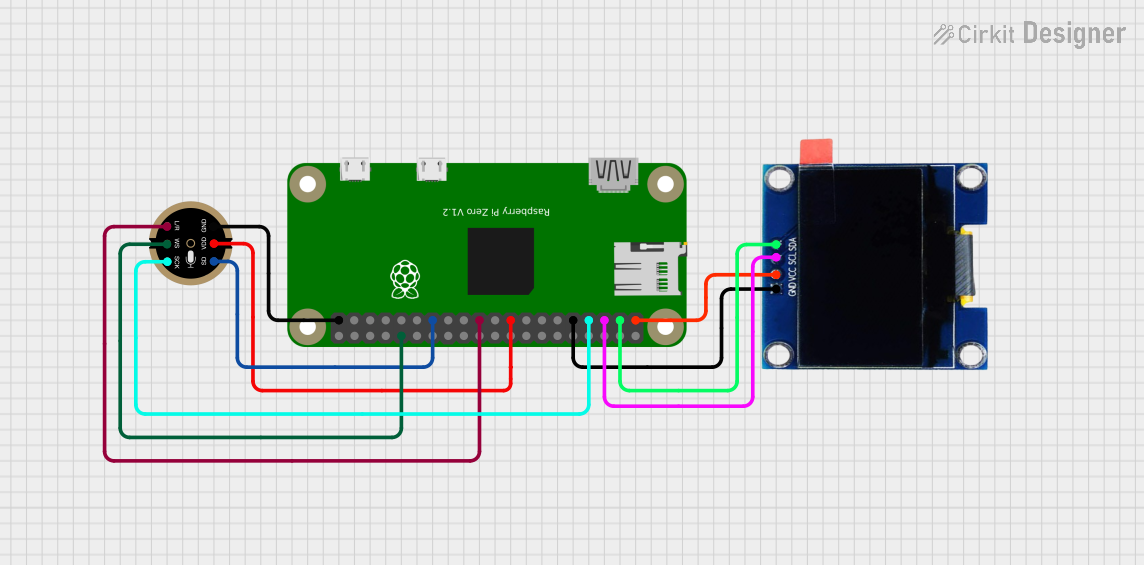
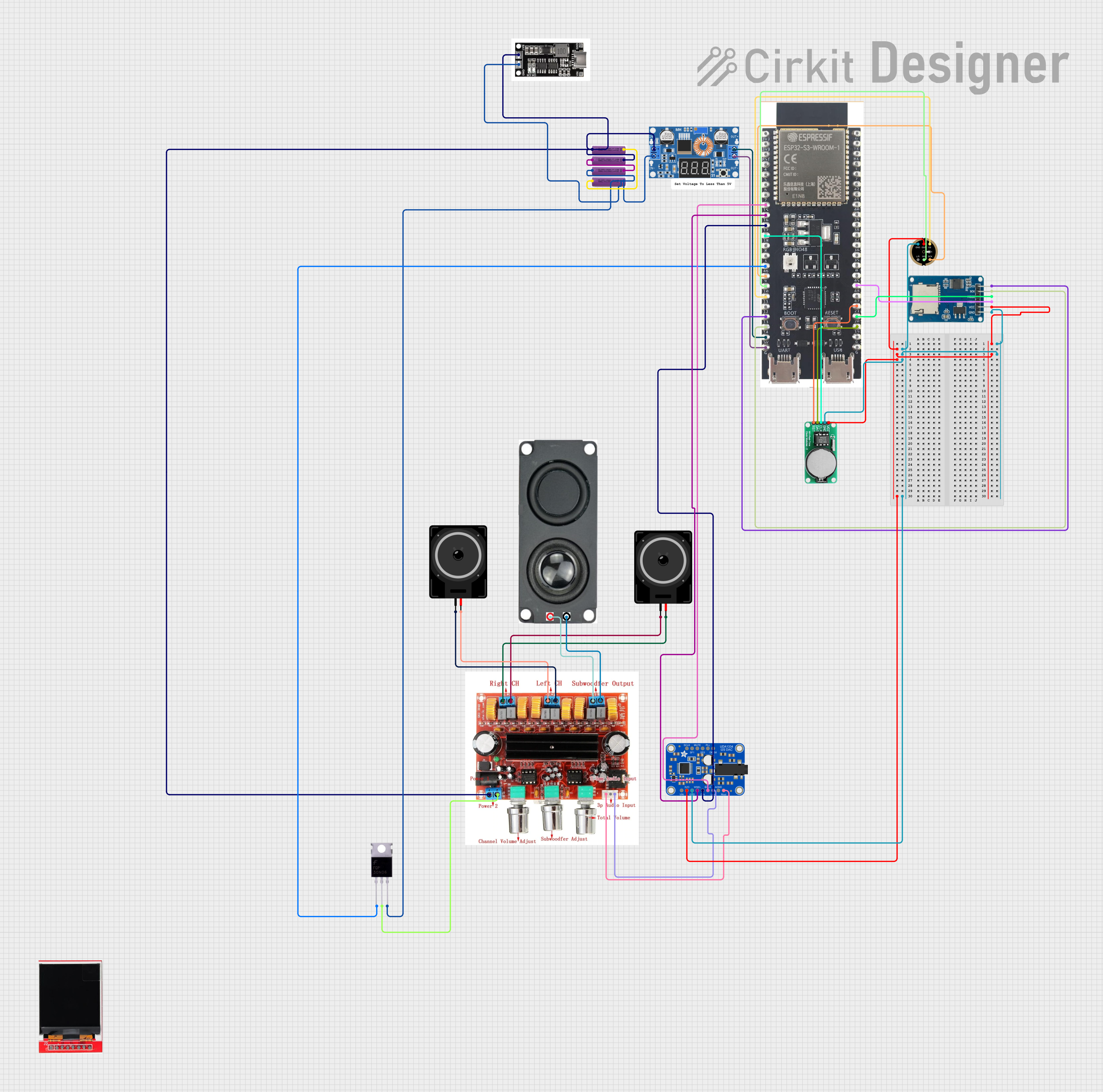
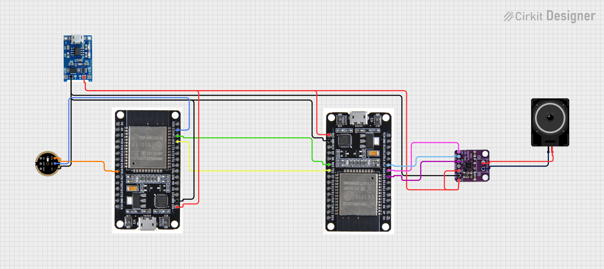

Explore Projects Built with i2s(MSM261S4030H0)
Common Applications
- Voice-controlled devices (e.g., smart speakers, virtual assistants)
- Audio recording systems
- IoT devices with audio input
- Noise monitoring and sound level detection
- Wearable devices with audio functionality
Technical Specifications
Key Technical Details
| Parameter | Value |
|---|---|
| Manufacturer | Arduino |
| Part ID | MSM261S4030H0 |
| Interface | I2S (Inter-IC Sound) |
| Supply Voltage (Vdd) | 1.8V to 3.3V |
| Current Consumption | 650 µA (typical) |
| Signal-to-Noise Ratio | 63 dB |
| Sensitivity | -26 dBFS ±1 dB |
| Frequency Response | 100 Hz to 10 kHz |
| Output Format | 24-bit I2S |
| Operating Temperature | -40°C to +85°C |
| Dimensions | 3.5 mm x 2.65 mm x 0.98 mm |
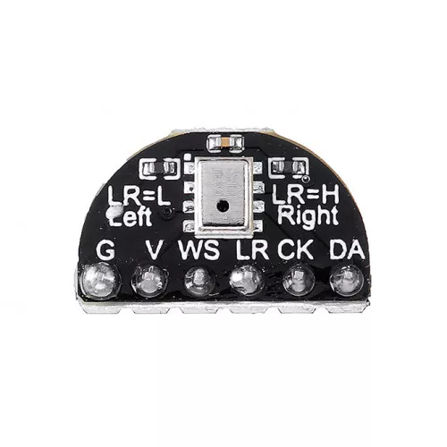
Pin Configuration and Descriptions
The MSM261S4030H0 has a total of 5 pins. Below is the pinout and description:
| Pin Name | Pin Number | Description |
|---|---|---|
| VDD | 1 | Power supply input (1.8V to 3.3V). |
| GND | 2 | Ground connection. |
| WS | 3 | Word Select (I2S frame synchronization signal). |
| SCK | 4 | Serial Clock (I2S clock signal). |
| SD | 5 | Serial Data (I2S audio data output). |
Usage Instructions
How to Use the MSM261S4030H0 in a Circuit
- Power Supply: Connect the VDD pin to a stable power source (1.8V to 3.3V) and the GND pin to the ground.
- I2S Interface: Connect the WS, SCK, and SD pins to the corresponding I2S interface pins on your microcontroller or audio processor.
- Bypass Capacitor: Place a 0.1 µF decoupling capacitor close to the VDD pin to ensure stable operation.
- Clock Signal: Ensure the SCK pin receives a proper clock signal (typically 1-3 MHz) from the microcontroller.
- Data Capture: Configure the microcontroller to read 24-bit I2S data from the SD pin.
Important Considerations
- Clock Synchronization: Ensure the SCK and WS signals are synchronized with the microcontroller's I2S peripheral.
- PCB Layout: Minimize noise by keeping the traces for the I2S signals short and away from high-frequency components.
- Power Supply Noise: Use a low-noise power supply to avoid interference with the microphone's performance.
Example Code for Arduino UNO
Below is an example of how to interface the MSM261S4030H0 with an Arduino UNO using the I2S library:
#include <I2S.h> // Include the I2S library for Arduino

void setup() {
  // Initialize serial communication for debugging
  Serial.begin(9600);

  // Start the I2S interface in receive mode
  if (!I2S.begin(I2S_PHILIPS_MODE, 44100, 24)) {
    Serial.println("Failed to initialize I2S!");
    while (1); // Halt execution if I2S initialization fails
  }

  Serial.println("I2S initialized successfully!");
}

void loop() {
  // Check if I2S data is available
  if (I2S.available()) {
    int sample = I2S.read(); // Read a 24-bit audio sample
    Serial.println(sample); // Print the sample to the serial monitor
  }
}
Notes:
- The
I2S.begin()function initializes the I2S interface in Philips mode with a 44.1 kHz sample rate and 24-bit resolution. - Ensure the Arduino UNO is connected to the MSM261S4030H0's I2S pins (WS, SCK, and SD) correctly.
Troubleshooting and FAQs
Common Issues and Solutions
No Audio Data Output
- Cause: Incorrect I2S pin connections.
- Solution: Verify that the WS, SCK, and SD pins are connected to the correct I2S pins on the microcontroller.
Distorted Audio
- Cause: Power supply noise or improper clock signal.
- Solution: Use a low-noise power supply and ensure the SCK signal is stable and within the recommended frequency range.
Microphone Not Detected
- Cause: I2S interface not initialized properly.
- Solution: Check the microcontroller's I2S configuration and ensure the
I2S.begin()function is called with the correct parameters.
Low Sensitivity
- Cause: Incorrect placement or orientation of the microphone.
- Solution: Ensure the microphone is placed close to the sound source and oriented correctly.
FAQs
Q: Can the MSM261S4030H0 be used with 5V systems?
A: No, the MSM261S4030H0 operates at a supply voltage of 1.8V to 3.3V. Use a voltage regulator or level shifter if interfacing with a 5V system.
Q: What is the maximum sampling rate supported?
A: The MSM261S4030H0 supports sampling rates up to 48 kHz.
Q: Can I use multiple microphones in a single system?
A: Yes, but ensure each microphone has a unique I2S configuration or use separate I2S peripherals to avoid data conflicts.
Q: Is an external ADC required?
A: No, the MSM261S4030H0 outputs digital audio data via the I2S interface, eliminating the need for an external ADC.