Cirkit Designer Logo
Cirkit Designer
Your all-in-one circuit design IDE
Home / 
Component Documentation

How to Use Arduino Mini (Rev5): Examples, Pinouts, and Specs

Image of Arduino Mini (Rev5)
Cirkit Designer LogoDesign with Arduino Mini (Rev5) in Cirkit Designer

Introduction

The Arduino Mini (Rev5) is a small, versatile microcontroller board based on the ATmega328. It is designed for use in space-constrained applications and is fully compatible with the Arduino programming language and integrated development environment (IDE). The Arduino Mini is ideal for embedding into projects where size is a critical factor, and it is often used in wearable technology, portable instruments, and custom embedded systems.

Explore Projects Built with Arduino Mini (Rev5)

Use Cirkit Designer to design, explore, and prototype these projects online. Some projects support real-time simulation. Click "Open Project" to start designing instantly!
Arduino Pro Mini-Based Battery-Powered Temperature and Laser Display System
Image of thermal temperture gun: A project utilizing Arduino Mini (Rev5) in a practical application
This circuit features an Arduino Pro Mini microcontroller interfaced with a USB Serial TTL for programming and power, a momentary switch for user input, and a 9V battery for power supply. It includes a KY-008 laser emitter, a 0.96" OLED display, and an MLX90614 temperature sensor, all connected to the Arduino for a potential temperature measurement and display application.
Cirkit Designer LogoOpen Project in Cirkit Designer
I2C-Controlled OLED Display with External EEPROM and Interactive Pushbuttons
Image of godmode: A project utilizing Arduino Mini (Rev5) in a practical application
This is a microcontroller-based interactive device featuring a Wemos D1 Mini, an OLED display, external EEPROM, and an I/O expander. It includes user input buttons and status LEDs, with potential MIDI interface capabilities.
Cirkit Designer LogoOpen Project in Cirkit Designer
Arduino Pro Mini Based CAN Bus Interface with OLED Display
Image of Fly Controller: A project utilizing Arduino Mini (Rev5) in a practical application
This circuit features an Arduino Pro Mini connected to an OLED display via I2C communication (SDA and SCL lines). The Arduino is also interfaced with an MCP2515 CAN controller, indicating the circuit's capability to communicate over a CAN network. Additionally, there are several terminal PCBs connected to various analog and digital pins of the Arduino, likely for sensor inputs or output controls.
Cirkit Designer LogoOpen Project in Cirkit Designer
Arduino Pro Mini Based GPS and Temperature Tracking System with Wireless Communication
Image of slave node: A project utilizing Arduino Mini (Rev5) in a practical application
This circuit features an Arduino Pro Mini as the central microcontroller, interfaced with a DS18B20 temperature sensor, a GPS NEO 6M module for location tracking, an ADXL345 accelerometer for motion detection, and an NRF24L01 module for wireless communication. The Arduino is powered by a 18650 Li-Ion battery through a voltage regulator, ensuring a stable power supply. A pushbutton is connected to the Arduino for user input, and resistors are used for pull-ups and current limiting purposes.
Cirkit Designer LogoOpen Project in Cirkit Designer

Explore Projects Built with Arduino Mini (Rev5)

Use Cirkit Designer to design, explore, and prototype these projects online. Some projects support real-time simulation. Click "Open Project" to start designing instantly!
Image of thermal temperture gun: A project utilizing Arduino Mini (Rev5) in a practical application
Arduino Pro Mini-Based Battery-Powered Temperature and Laser Display System
This circuit features an Arduino Pro Mini microcontroller interfaced with a USB Serial TTL for programming and power, a momentary switch for user input, and a 9V battery for power supply. It includes a KY-008 laser emitter, a 0.96" OLED display, and an MLX90614 temperature sensor, all connected to the Arduino for a potential temperature measurement and display application.
Cirkit Designer LogoOpen Project in Cirkit Designer
Image of godmode: A project utilizing Arduino Mini (Rev5) in a practical application
I2C-Controlled OLED Display with External EEPROM and Interactive Pushbuttons
This is a microcontroller-based interactive device featuring a Wemos D1 Mini, an OLED display, external EEPROM, and an I/O expander. It includes user input buttons and status LEDs, with potential MIDI interface capabilities.
Cirkit Designer LogoOpen Project in Cirkit Designer
Image of Fly Controller: A project utilizing Arduino Mini (Rev5) in a practical application
Arduino Pro Mini Based CAN Bus Interface with OLED Display
This circuit features an Arduino Pro Mini connected to an OLED display via I2C communication (SDA and SCL lines). The Arduino is also interfaced with an MCP2515 CAN controller, indicating the circuit's capability to communicate over a CAN network. Additionally, there are several terminal PCBs connected to various analog and digital pins of the Arduino, likely for sensor inputs or output controls.
Cirkit Designer LogoOpen Project in Cirkit Designer
Image of slave node: A project utilizing Arduino Mini (Rev5) in a practical application
Arduino Pro Mini Based GPS and Temperature Tracking System with Wireless Communication
This circuit features an Arduino Pro Mini as the central microcontroller, interfaced with a DS18B20 temperature sensor, a GPS NEO 6M module for location tracking, an ADXL345 accelerometer for motion detection, and an NRF24L01 module for wireless communication. The Arduino is powered by a 18650 Li-Ion battery through a voltage regulator, ensuring a stable power supply. A pushbutton is connected to the Arduino for user input, and resistors are used for pull-ups and current limiting purposes.
Cirkit Designer LogoOpen Project in Cirkit Designer

Common Applications and Use Cases

  • Wearable devices
  • Portable electronics
  • Prototyping for compact systems
  • Educational projects and hobbyist applications
  • Custom embedded solutions

Technical Specifications

Key Technical Details

  • Microcontroller: ATmega328
  • Operating Voltage: 5V
  • Input Voltage (recommended): 7-9V
  • Input Voltage (limits): 6-20V
  • Digital I/O Pins: 14 (of which 6 provide PWM output)
  • Analog Input Pins: 8
  • DC Current per I/O Pin: 40 mA
  • Flash Memory: 32 KB (ATmega328) of which 2 KB used by bootloader
  • SRAM: 2 KB (ATmega328)
  • EEPROM: 1 KB (ATmega328)
  • Clock Speed: 16 MHz

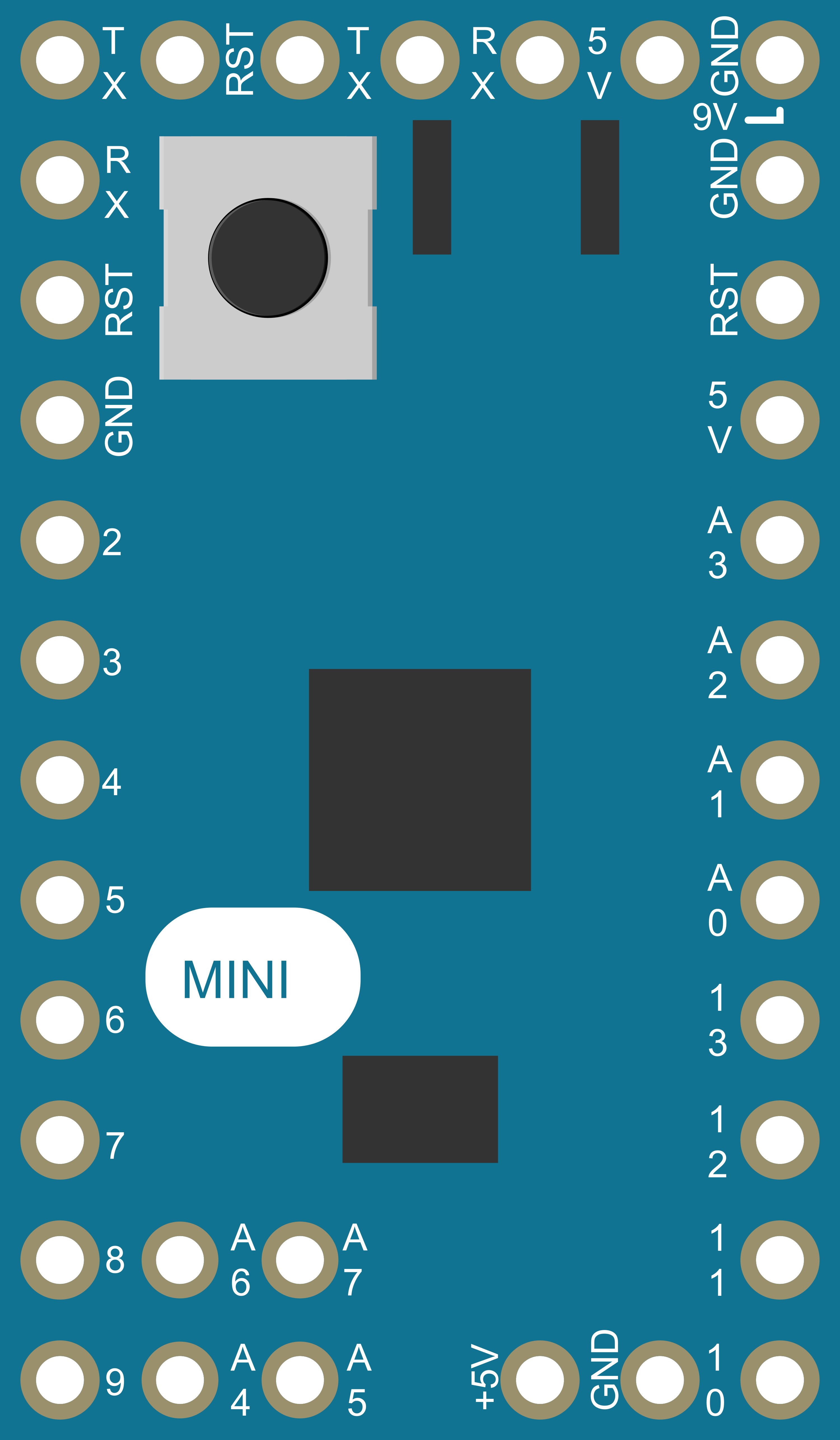
Pin Configuration and Descriptions

Pin Number Function Description
1 RESET Used to reset the microcontroller
2-13 Digital Pins Digital input/output pins, PWM on 3, 5, 6, 9, 10, and 11
14-21 Analog Pins Analog input pins (A0-A7)
22 GND Ground pin
23 AREF Analog reference voltage for the ADC
24 3V3 3.3V output (from FTDI chip)
25 DTR Data Terminal Ready, used for auto-reset
26 TXD Transmit Data, used for serial communication
27 RXD Receive Data, used for serial communication
28 GND Ground pin
29 VCC Positive supply voltage
30 OSC1 Oscillator pin
31 OSC2 Oscillator pin

Usage Instructions

How to Use the Component in a Circuit

  1. Powering the Arduino Mini: Connect a 7-9V power supply to the RAW input pin and GND. Alternatively, you can supply regulated 5V to the VCC pin.

  2. Programming the Arduino Mini: To program the Arduino Mini, you will need an external USB-to-serial converter. Connect the converter's TX to the Mini's RX, RX to TX, DTR to DTR, VCC to VCC, and GND to GND.

  3. Connecting I/O Devices: Use the digital and analog pins to connect sensors, actuators, and other components. Ensure that the devices you connect are compatible with the voltage and current specifications of the Arduino Mini's pins.

Important Considerations and Best Practices

  • Always disconnect the Arduino Mini from power sources before making or altering connections.
  • Use a current-limiting resistor when connecting LEDs to digital pins to prevent damage.
  • Avoid supplying voltage higher than 20V to the RAW pin, as it may damage the board.
  • Ensure that the total current drawn from all I/O pins does not exceed the limit specified in the technical specifications.

Troubleshooting and FAQs

Common Issues

  • Arduino Mini not recognized by the computer: Ensure that the USB-to-serial converter drivers are installed and that the connections are correct.
  • Sketch not uploading: Check the board and port settings in the Arduino IDE, and ensure that the DTR pin is connected to enable auto-reset during the upload process.
  • Unexpected behavior in circuits: Verify that all components are correctly wired and that the power supply is stable and within the recommended voltage range.

Solutions and Tips for Troubleshooting

  • Double-check wiring, especially the connections between the USB-to-serial converter and the Arduino Mini.
  • Use a multimeter to check for shorts or open circuits on the board.
  • If the Arduino Mini is unresponsive, try manually resetting the board just before uploading a sketch.
  • Consult the Arduino forums and community for help with specific issues.

FAQs

Q: Can I power the Arduino Mini with a battery? A: Yes, you can power it with a battery, provided the voltage is within the 6-20V limit for the RAW pin or regulated 5V for the VCC pin.

Q: How do I connect the Arduino Mini to a breadboard? A: Since the Arduino Mini does not come with standard headers, you will need to solder headers or wires to the pins to connect it to a breadboard.

Q: Does the Arduino Mini have onboard USB? A: No, the Arduino Mini requires an external USB-to-serial converter for programming and communication with a computer.

Example Code for Arduino UNO

Here is a simple example of blinking an LED connected to pin 13 of the Arduino Mini:

// Pin 13 has an LED connected on most Arduino boards.
int led = 13;

// the setup routine runs once when you press reset:
void setup() {
  // initialize the digital pin as an output.
  pinMode(led, OUTPUT);
}

// the loop routine runs over and over again forever:
void loop() {
  digitalWrite(led, HIGH);   // turn the LED on (HIGH is the voltage level)
  delay(1000);               // wait for a second
  digitalWrite(led, LOW);    // turn the LED off by making the voltage LOW
  delay(1000);               // wait for a second
}

Remember to select the correct board and port before uploading the code to the Arduino Mini.