How to Use ggp: Examples, Pinouts, and Specs
Introduction
The GGP (Generalized Gate Protocol) is a specialized circuit component designed for use in quantum computing applications. Manufactured by Texas Instruments under the part ID INA114, this component facilitates the implementation of quantum gates, which are the fundamental building blocks of quantum circuits. The GGP is engineered to provide precise control and high fidelity in quantum gate operations, making it an essential component in advanced quantum computing systems.
Explore Projects Built with ggp
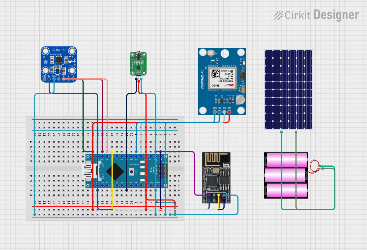

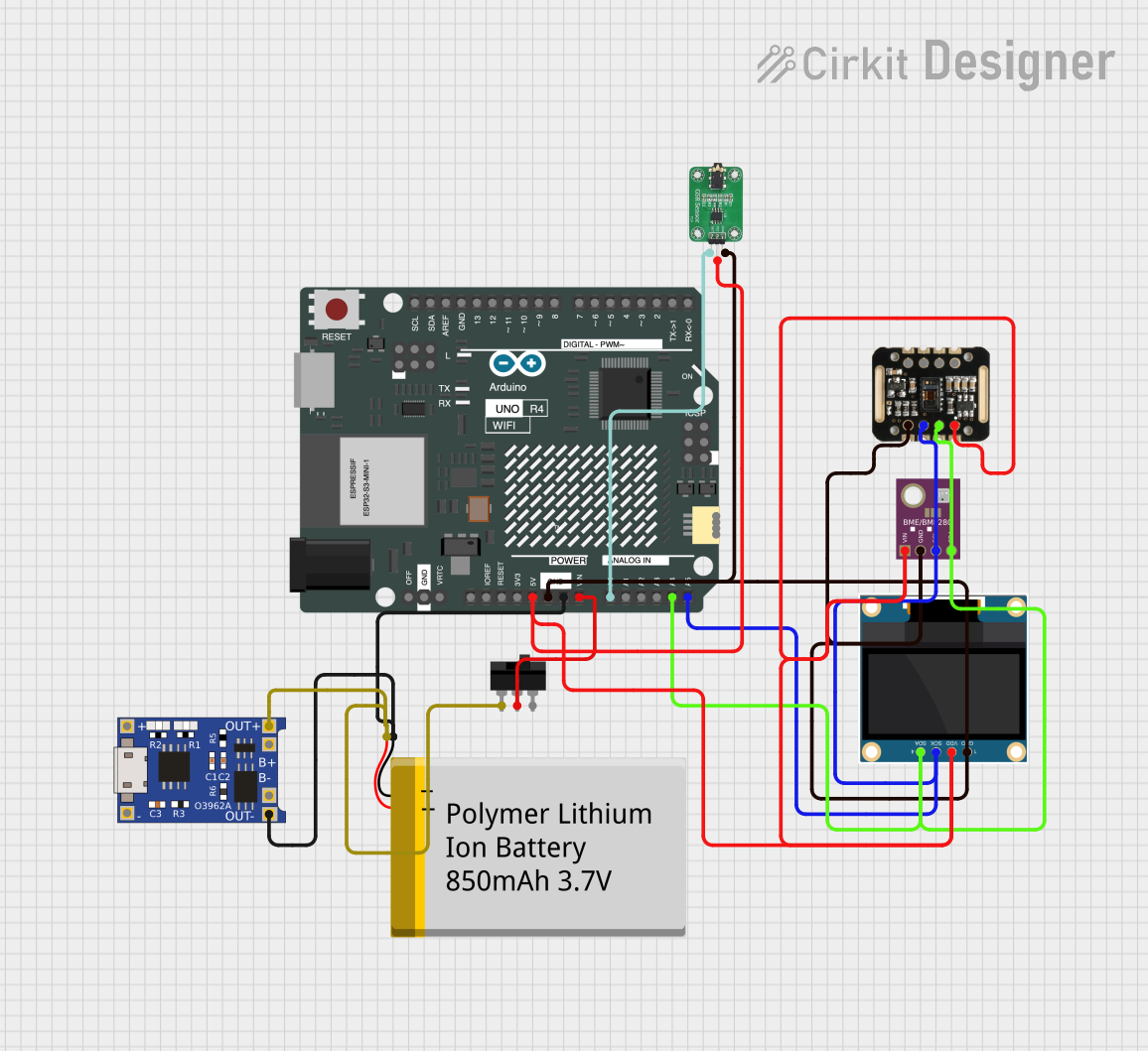
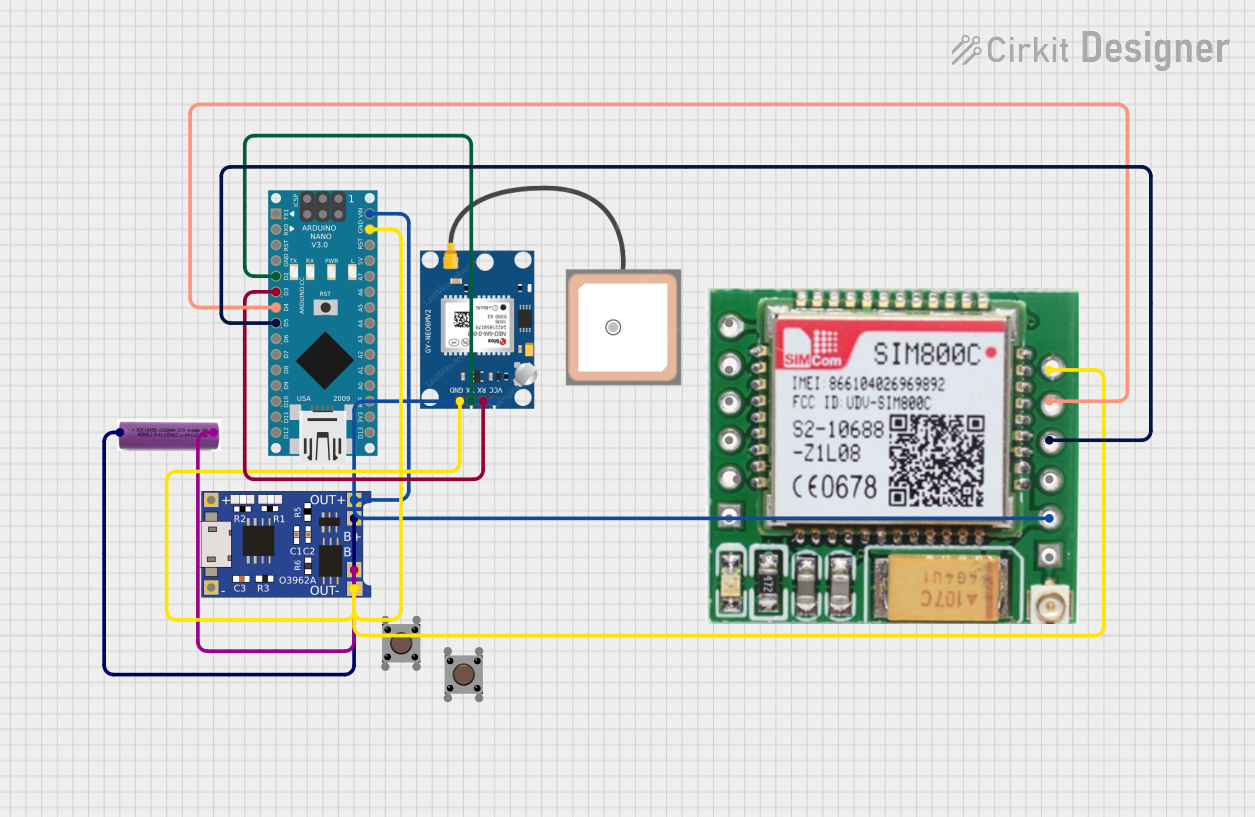
Explore Projects Built with ggp
Common Applications and Use Cases
- Quantum computing systems for research and development
- Implementation of quantum algorithms
- Quantum error correction circuits
- High-fidelity quantum gate operations
- Quantum cryptography and secure communication systems
Technical Specifications
The GGP component is designed to meet the demanding requirements of quantum computing. Below are its key technical specifications:
Key Technical Details
- Manufacturer: Texas Instruments
- Part ID: INA114
- Operating Voltage: 3.3V to 5V
- Power Consumption: < 10 mW
- Quantum Gate Fidelity: ≥ 99.9%
- Operating Temperature Range: -40°C to 85°C
- Interface: Compatible with standard quantum control systems
- Package Type: DIP-8 or SOIC-8
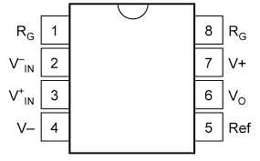
Pin Configuration and Descriptions
The GGP component features an 8-pin configuration. The table below provides details for each pin:
| Pin Number | Pin Name | Description |
|---|---|---|
| 1 | V+ | Positive power supply input (3.3V to 5V). |
| 2 | IN+ | Non-inverting input for quantum gate control signals. |
| 3 | IN- | Inverting input for quantum gate control signals. |
| 4 | GND | Ground connection. |
| 5 | OUT | Output signal for quantum gate operation. |
| 6 | QCTRL | Quantum control input for gate configuration. |
| 7 | CLK | Clock input for timing synchronization. |
| 8 | V- | Negative power supply input (optional, for dual-supply operation). |
Usage Instructions
The GGP component is designed to be integrated into quantum computing circuits with ease. Below are the steps and best practices for using the component:
How to Use the Component in a Circuit
- Power Supply: Connect the V+ pin to a stable 3.3V or 5V power source. If dual-supply operation is required, connect the V- pin to the negative voltage source.
- Signal Inputs: Connect the IN+ and IN- pins to the quantum control signals. Ensure that the signals are within the specified voltage range.
- Quantum Control: Use the QCTRL pin to configure the desired quantum gate operation. This pin can be connected to a microcontroller or quantum control system.
- Clock Synchronization: Provide a clock signal to the CLK pin for precise timing of quantum gate operations.
- Output: The OUT pin provides the output signal for the quantum gate. Connect this pin to the next stage of the quantum circuit.
Important Considerations and Best Practices
- Ensure that the power supply is stable and free from noise to maintain high gate fidelity.
- Use proper grounding techniques to minimize interference and maintain signal integrity.
- Avoid exceeding the specified voltage and temperature limits to prevent damage to the component.
- For optimal performance, use the component in a temperature-controlled environment.
Example Code for Arduino UNO
Although the GGP is primarily used in quantum computing, it can be interfaced with an Arduino UNO for basic control and testing purposes. Below is an example code snippet:
// Example code to control the GGP component using Arduino UNO
// This code configures the QCTRL pin and provides a clock signal to the CLK pin.

const int QCTRL_PIN = 7; // Pin connected to QCTRL
const int CLK_PIN = 8;   // Pin connected to CLK

void setup() {
  pinMode(QCTRL_PIN, OUTPUT); // Set QCTRL pin as output
  pinMode(CLK_PIN, OUTPUT);   // Set CLK pin as output

  // Initialize QCTRL to LOW
  digitalWrite(QCTRL_PIN, LOW);
}

void loop() {
  // Configure the QCTRL pin to enable a specific quantum gate
  digitalWrite(QCTRL_PIN, HIGH); // Activate QCTRL
  delay(100);                    // Wait for 100 ms

  // Generate a clock signal on the CLK pin
  digitalWrite(CLK_PIN, HIGH);   // Set CLK HIGH
  delayMicroseconds(10);         // Wait for 10 microseconds
  digitalWrite(CLK_PIN, LOW);    // Set CLK LOW
  delayMicroseconds(10);         // Wait for 10 microseconds
}
Troubleshooting and FAQs
Common Issues Users Might Face
No Output Signal:
- Cause: Incorrect power supply or improper connections.
- Solution: Verify that the V+ and GND pins are connected to a stable power source. Check all connections.
Low Gate Fidelity:
- Cause: Noisy power supply or improper grounding.
- Solution: Use a low-noise power supply and ensure proper grounding techniques.
Component Overheating:
- Cause: Exceeding the specified voltage or operating temperature range.
- Solution: Ensure that the voltage and temperature are within the specified limits.
Clock Signal Issues:
- Cause: Incorrect clock frequency or unstable clock source.
- Solution: Verify the clock signal and ensure it meets the component's requirements.
Solutions and Tips for Troubleshooting
- Use an oscilloscope to monitor the input and output signals for debugging.
- Double-check the pin connections and ensure they match the circuit design.
- If the component is not functioning as expected, consult the Texas Instruments datasheet for additional details.
By following this documentation, users can effectively integrate and utilize the GGP component in their quantum computing projects.