Cirkit Designer Logo
Cirkit Designer
Your all-in-one circuit design IDE
Home / 
Component Documentation

How to Use vibration sensor: Examples, Pinouts, and Specs

Image of vibration sensor
Cirkit Designer LogoDesign with vibration sensor in Cirkit Designer

Introduction

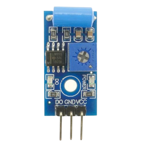
The vibration sensor is a device designed to detect and measure vibrations or oscillations in an object or environment. Manufactured by Sensor, this component is widely used in applications where monitoring physical movement or disturbances is critical. Its compact design and reliable performance make it suitable for a variety of use cases, including:

  • Security systems (e.g., detecting unauthorized access or tampering)
  • Industrial machinery monitoring (e.g., detecting abnormal vibrations in equipment)
  • Environmental monitoring (e.g., measuring seismic activity or structural vibrations)
  • Consumer electronics (e.g., motion-based input devices)

This versatile sensor is an essential tool for engineers and hobbyists alike, offering a simple yet effective way to monitor vibrations in real-time.

Explore Projects Built with vibration sensor

Use Cirkit Designer to design, explore, and prototype these projects online. Some projects support real-time simulation. Click "Open Project" to start designing instantly!
Arduino Nano-Based Vibration Detection System with SIM800L GSM Module
Image of asd: A project utilizing vibration sensor in a practical application
This circuit is designed to detect vibrations using the SW-420 Vibration Sensor and communicate the detection events via the Sim800l GSM module. The Arduino Nano serves as the central controller, interfacing with the vibration sensor on its digital pin D4 and with the Sim800l module through serial communication using pins D0/RX and D1/TX. The circuit is likely intended for remote monitoring of vibrations, potentially for security or machinery fault detection applications.
Cirkit Designer LogoOpen Project in Cirkit Designer
Arduino Nano-Based Haptic Navigation Shoe for the Visually Impaired with Bluetooth Connectivity
Image of Blind shoes layer 2: A project utilizing vibration sensor in a practical application
This circuit is a haptic navigation system for the visually impaired, utilizing an Arduino Nano to interface with various sensors including a rain sensor, ultrasonic sensor, accelerometer, radar sensor, and Bluetooth module. The system provides feedback through vibration motors and a buzzer, and sends sensor data to a mobile app via Bluetooth for tracking and alerts.
Cirkit Designer LogoOpen Project in Cirkit Designer
Arduino Nano-Based Wearable Gesture Control Interface with Bluetooth Connectivity
Image of spine: A project utilizing vibration sensor in a practical application
This is a battery-powered sensor system with Bluetooth communication, featuring an Arduino Nano for control, an MPU-6050 for motion sensing, and an HC-05 module for wireless data transmission. It includes a vibration motor for haptic feedback, a flex resistor as an additional sensor, and a piezo speaker and LED for alerts or status indication.
Cirkit Designer LogoOpen Project in Cirkit Designer
Arduino UNO-Based GPS and GSM-Enabled Vibration Sensor System with Motor Control
Image of gps based accident detection and alert system: A project utilizing vibration sensor in a practical application
This circuit is a GPS-based tracking system with vibration detection and motor control capabilities. It uses an Arduino UNO to interface with a Neo 6M GPS module for location data, a Sim800l module for GSM communication, an ADXL345 accelerometer for motion sensing, and an SW-420 vibration sensor to detect vibrations. The system also includes a motor driver to control two DC motors and a buzzer for alerts, all powered by a 5V battery.
Cirkit Designer LogoOpen Project in Cirkit Designer

Explore Projects Built with vibration sensor

Use Cirkit Designer to design, explore, and prototype these projects online. Some projects support real-time simulation. Click "Open Project" to start designing instantly!
Image of asd: A project utilizing vibration sensor in a practical application
Arduino Nano-Based Vibration Detection System with SIM800L GSM Module
This circuit is designed to detect vibrations using the SW-420 Vibration Sensor and communicate the detection events via the Sim800l GSM module. The Arduino Nano serves as the central controller, interfacing with the vibration sensor on its digital pin D4 and with the Sim800l module through serial communication using pins D0/RX and D1/TX. The circuit is likely intended for remote monitoring of vibrations, potentially for security or machinery fault detection applications.
Cirkit Designer LogoOpen Project in Cirkit Designer
Image of Blind shoes layer 2: A project utilizing vibration sensor in a practical application
Arduino Nano-Based Haptic Navigation Shoe for the Visually Impaired with Bluetooth Connectivity
This circuit is a haptic navigation system for the visually impaired, utilizing an Arduino Nano to interface with various sensors including a rain sensor, ultrasonic sensor, accelerometer, radar sensor, and Bluetooth module. The system provides feedback through vibration motors and a buzzer, and sends sensor data to a mobile app via Bluetooth for tracking and alerts.
Cirkit Designer LogoOpen Project in Cirkit Designer
Image of spine: A project utilizing vibration sensor in a practical application
Arduino Nano-Based Wearable Gesture Control Interface with Bluetooth Connectivity
This is a battery-powered sensor system with Bluetooth communication, featuring an Arduino Nano for control, an MPU-6050 for motion sensing, and an HC-05 module for wireless data transmission. It includes a vibration motor for haptic feedback, a flex resistor as an additional sensor, and a piezo speaker and LED for alerts or status indication.
Cirkit Designer LogoOpen Project in Cirkit Designer
Image of gps based accident detection and alert system: A project utilizing vibration sensor in a practical application
Arduino UNO-Based GPS and GSM-Enabled Vibration Sensor System with Motor Control
This circuit is a GPS-based tracking system with vibration detection and motor control capabilities. It uses an Arduino UNO to interface with a Neo 6M GPS module for location data, a Sim800l module for GSM communication, an ADXL345 accelerometer for motion sensing, and an SW-420 vibration sensor to detect vibrations. The system also includes a motor driver to control two DC motors and a buzzer for alerts, all powered by a 5V battery.
Cirkit Designer LogoOpen Project in Cirkit Designer

Technical Specifications

Below are the key technical details for the vibration sensor:

Parameter Value
Manufacturer Sensor
Part ID Vibration Sensor
Operating Voltage 3.3V to 5V
Output Type Digital or Analog (depending on model)
Sensitivity Adjustable (via onboard potentiometer)
Operating Temperature -20°C to 70°C
Dimensions 32mm x 14mm x 8mm

Pin Configuration and Descriptions

The vibration sensor typically has three pins, as described in the table below:

Pin Name Description
1 VCC Power supply pin (3.3V to 5V)
2 GND Ground connection
3 OUT Output pin (provides digital or analog signal based on vibration)
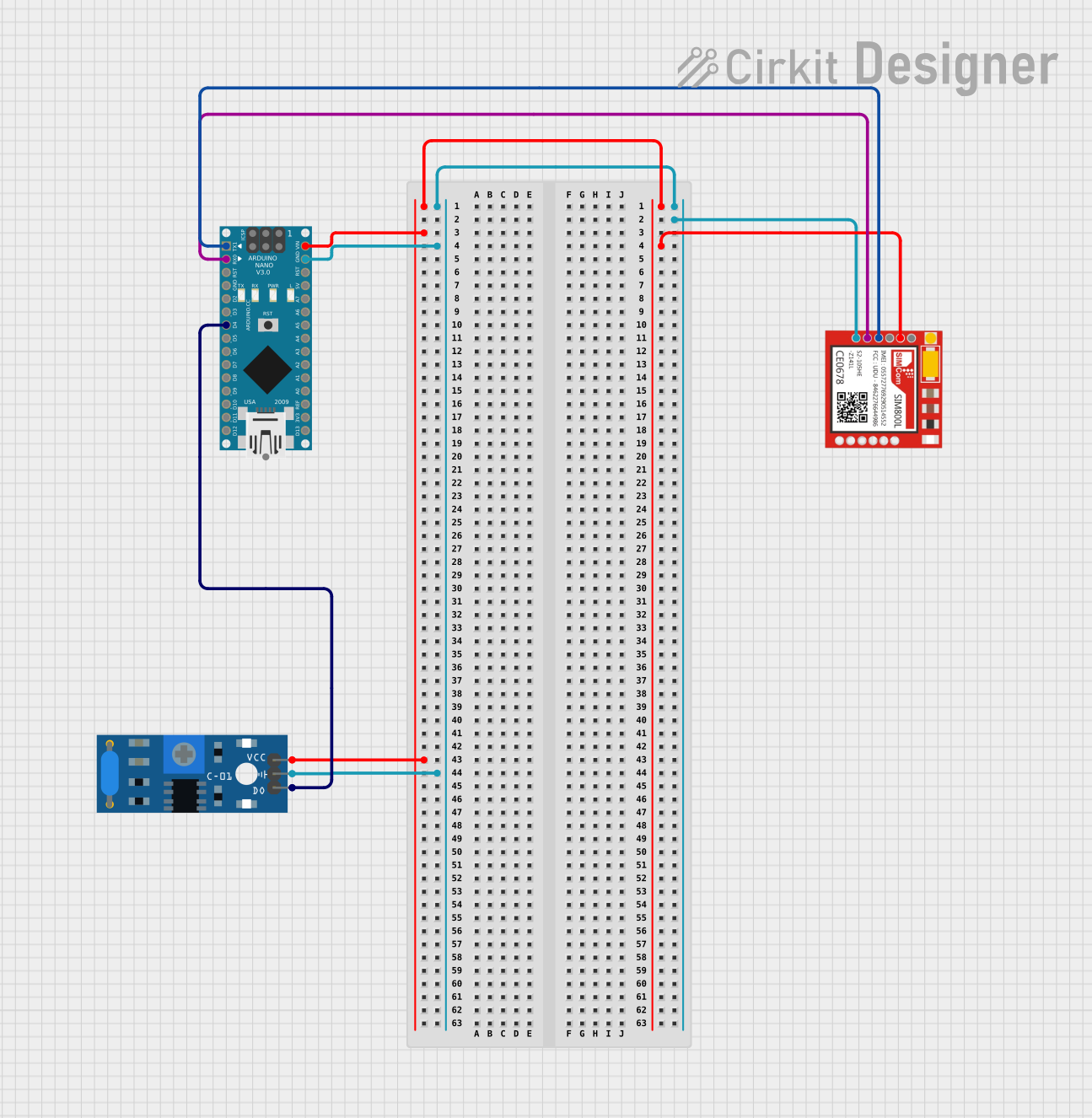
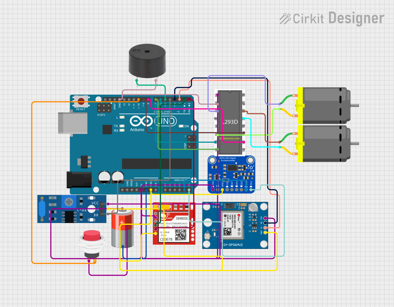
Usage Instructions

How to Use the Vibration Sensor in a Circuit

  1. Power the Sensor: Connect the VCC pin to a 3.3V or 5V power source and the GND pin to the ground of your circuit.
  2. Connect the Output: Attach the OUT pin to a microcontroller's input pin (e.g., an Arduino UNO) or an external monitoring device.
  3. Adjust Sensitivity: If the sensor includes an onboard potentiometer, adjust it to set the desired sensitivity level for vibration detection.
  4. Read the Output: Monitor the OUT pin for changes in signal. A high signal typically indicates vibration detection, while a low signal indicates no vibration.

Important Considerations and Best Practices

  • Power Supply: Ensure the sensor operates within its specified voltage range (3.3V to 5V) to avoid damage.
  • Mounting: Secure the sensor firmly to the surface being monitored to ensure accurate vibration detection.
  • Noise Filtering: If the environment has significant electrical noise, consider adding a capacitor between the VCC and GND pins to stabilize the power supply.
  • Signal Processing: For analog output models, use an analog-to-digital converter (ADC) to process the signal accurately.

Example: Connecting to an Arduino UNO

Below is an example of how to connect and use the vibration sensor with an Arduino UNO:

Circuit Connections

  • VCC → 5V pin on Arduino
  • GND → GND pin on Arduino
  • OUT → Digital pin 2 on Arduino

Arduino Code

// Vibration Sensor Example Code
// This code reads the digital output of the vibration sensor and prints
// a message to the Serial Monitor when vibration is detected.

const int sensorPin = 2; // Pin connected to the OUT pin of the vibration sensor
int sensorState = 0;     // Variable to store the sensor's state

void setup() {
  pinMode(sensorPin, INPUT); // Set the sensor pin as an input
  Serial.begin(9600);        // Initialize serial communication at 9600 baud
}

void loop() {
  sensorState = digitalRead(sensorPin); // Read the sensor's output state

  if (sensorState == HIGH) {
    // If vibration is detected, print a message
    Serial.println("Vibration detected!");
  } else {
    // If no vibration is detected, print a different message
    Serial.println("No vibration.");
  }

  delay(500); // Wait for 500ms before reading again
}

Troubleshooting and FAQs

Common Issues and Solutions

  1. No Output Signal:

    • Cause: Incorrect wiring or loose connections.
    • Solution: Double-check all connections, ensuring the VCC, GND, and OUT pins are properly connected.
  2. False Positives (Vibration Detected When None Exists):

    • Cause: High sensitivity or electrical noise.
    • Solution: Adjust the potentiometer to reduce sensitivity or add a capacitor to filter noise.
  3. Sensor Not Responding to Vibrations:

    • Cause: Low sensitivity or improper mounting.
    • Solution: Increase sensitivity using the potentiometer and ensure the sensor is securely mounted to the vibrating surface.
  4. Output Signal is Unstable:

    • Cause: Power supply fluctuations.
    • Solution: Use a stable power source and consider adding a decoupling capacitor.

FAQs

Q1: Can this sensor detect very small vibrations?
A1: Yes, the sensitivity can be adjusted using the onboard potentiometer to detect even minor vibrations.

Q2: Is this sensor compatible with 3.3V microcontrollers like ESP32?
A2: Yes, the sensor operates within a voltage range of 3.3V to 5V, making it compatible with 3.3V systems.

Q3: Can I use multiple vibration sensors in the same circuit?
A3: Yes, you can use multiple sensors, but ensure each sensor has a unique input pin on your microcontroller.

Q4: Does the sensor work outdoors?
A4: While the sensor can operate in a wide temperature range, it is not waterproof. Use appropriate enclosures for outdoor applications.

This documentation provides all the necessary details to get started with the vibration sensor. For further assistance, refer to the manufacturer's datasheet or contact technical support.