How to Use moto driver 6600: Examples, Pinouts, and Specs
Introduction
The Moto Driver 6600 is a versatile motor driver IC designed to control both DC motors and stepper motors. It provides the necessary current and voltage to drive motors efficiently based on input control signals. This component is widely used in robotics, automation systems, and other motor control applications due to its reliability and ease of use.
Explore Projects Built with moto driver 6600


Explore Projects Built with moto driver 6600
Common Applications and Use Cases
- Robotics: Driving wheels or robotic arms
- CNC machines: Controlling stepper motors for precision movement
- Conveyor belts: Managing DC motor speed and direction
- DIY projects: Motorized toys, automated curtains, and more
Technical Specifications
The Moto Driver 6600 is designed to handle a wide range of motor control requirements. Below are its key technical details:
| Parameter | Value |
|---|---|
| Operating Voltage | 4.5V to 36V |
| Output Current | Up to 3A per channel |
| Channels | Dual-channel (can drive 2 motors) |
| Control Logic Voltage | 3.3V or 5V compatible |
| PWM Frequency | Up to 100 kHz |
| Motor Types Supported | DC motors, Stepper motors |
| Thermal Protection | Built-in thermal shutdown |
| Overcurrent Protection | Yes |
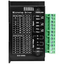
Pin Configuration and Descriptions
The Moto Driver 6600 typically comes in a 16-pin package. Below is the pin configuration:
| Pin Number | Pin Name | Description |
|---|---|---|
| 1 | IN1 | Input signal for controlling Motor 1 direction |
| 2 | IN2 | Input signal for controlling Motor 1 direction |
| 3 | ENA | Enable pin for Motor 1 (PWM input for speed control) |
| 4 | OUT1 | Output pin connected to Motor 1 terminal |
| 5 | OUT2 | Output pin connected to Motor 1 terminal |
| 6 | GND | Ground connection |
| 7 | VCC | Power supply for the motor driver (4.5V to 36V) |
| 8 | VM | Motor power supply |
| 9 | OUT3 | Output pin connected to Motor 2 terminal |
| 10 | OUT4 | Output pin connected to Motor 2 terminal |
| 11 | ENB | Enable pin for Motor 2 (PWM input for speed control) |
| 12 | IN3 | Input signal for controlling Motor 2 direction |
| 13 | IN4 | Input signal for controlling Motor 2 direction |
| 14 | NC | No connection |
| 15 | NC | No connection |
| 16 | GND | Ground connection |
Usage Instructions
How to Use the Moto Driver 6600 in a Circuit
Power Connections:
- Connect the
VCCpin to a power source (4.5V to 36V) suitable for your motor. - Connect the
GNDpin to the ground of your circuit. - If your motor requires a separate power supply, connect it to the
VMpin.
- Connect the
Motor Connections:
- Connect the motor terminals to the
OUT1andOUT2pins for Motor 1, andOUT3andOUT4pins for Motor 2.
- Connect the motor terminals to the
Control Signals:
- Use the
IN1andIN2pins to control the direction of Motor 1, andIN3andIN4for Motor 2. - Apply a PWM signal to the
ENApin for Motor 1 and theENBpin for Motor 2 to control their speed.
- Use the
Logic Voltage:
- Ensure the control logic voltage (3.3V or 5V) matches the microcontroller or control circuit you are using.
Important Considerations and Best Practices
- Heat Dissipation: The Moto Driver 6600 can generate heat during operation. Use a heat sink or ensure proper ventilation to prevent overheating.
- Current Limits: Do not exceed the maximum current rating of 3A per channel to avoid damaging the IC.
- Decoupling Capacitors: Place a decoupling capacitor (e.g., 100 µF) near the
VCCandVMpins to stabilize the power supply. - Protection Diodes: If your motor generates back EMF, consider adding flyback diodes to protect the driver.
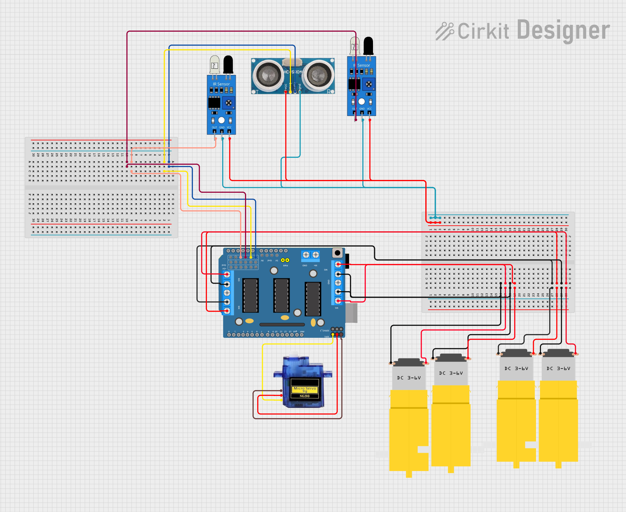
Example: Using Moto Driver 6600 with Arduino UNO
Below is an example of how to control a DC motor using the Moto Driver 6600 and an Arduino UNO:
// Define motor control pins
const int IN1 = 9;  // Motor 1 direction control pin
const int IN2 = 8;  // Motor 1 direction control pin
const int ENA = 10; // Motor 1 speed control (PWM pin)

void setup() {
  // Set motor control pins as outputs
  pinMode(IN1, OUTPUT);
  pinMode(IN2, OUTPUT);
  pinMode(ENA, OUTPUT);
}

void loop() {
  // Rotate motor clockwise
  digitalWrite(IN1, HIGH); // Set IN1 high
  digitalWrite(IN2, LOW);  // Set IN2 low
  analogWrite(ENA, 128);   // Set speed to 50% (PWM value: 128 out of 255)
  delay(2000);             // Run motor for 2 seconds

  // Rotate motor counterclockwise
  digitalWrite(IN1, LOW);  // Set IN1 low
  digitalWrite(IN2, HIGH); // Set IN2 high
  analogWrite(ENA, 128);   // Maintain speed at 50%
  delay(2000);             // Run motor for 2 seconds

  // Stop motor
  digitalWrite(IN1, LOW);  // Set IN1 low
  digitalWrite(IN2, LOW);  // Set IN2 low
  analogWrite(ENA, 0);     // Set speed to 0
  delay(2000);             // Wait for 2 seconds
}
Troubleshooting and FAQs
Common Issues and Solutions
Motor Not Running:
- Cause: Incorrect wiring or loose connections.
- Solution: Double-check all connections, especially the motor terminals and power supply.
Overheating:
- Cause: Excessive current draw or insufficient cooling.
- Solution: Ensure the motor's current requirements are within the IC's limits. Add a heat sink or improve ventilation.
Erratic Motor Behavior:
- Cause: Noise in the power supply or control signals.
- Solution: Add decoupling capacitors near the power pins and use shielded cables for control signals.
PWM Signal Not Working:
- Cause: Incorrect PWM frequency or duty cycle.
- Solution: Verify the PWM signal is within the IC's supported frequency range (up to 100 kHz).
FAQs
Q1: Can the Moto Driver 6600 drive two stepper motors simultaneously?
A1: No, the Moto Driver 6600 can drive one stepper motor or two DC motors simultaneously.
Q2: What happens if the input voltage exceeds 36V?
A2: Exceeding 36V can permanently damage the IC. Always ensure the input voltage is within the specified range.
Q3: Can I use the Moto Driver 6600 with a 3.3V microcontroller?
A3: Yes, the control logic is compatible with both 3.3V and 5V systems.
Q4: Is it necessary to use external diodes for protection?
A4: The IC has built-in protection, but external flyback diodes are recommended for high-inductance motors.