How to Use Micro USB to USB cable: Examples, Pinouts, and Specs
Introduction
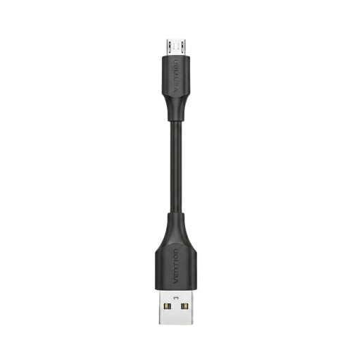
The Micro USB to USB cable is a versatile and widely used electronic component designed to connect devices with a Micro USB port to standard USB ports. It facilitates data transfer, device synchronization, and charging. This cable is commonly used with smartphones, tablets, power banks, cameras, and various other electronic devices.
Explore Projects Built with Micro USB to USB cable


Explore Projects Built with Micro USB to USB cable
Common Applications and Use Cases
- Charging mobile devices such as smartphones, tablets, and power banks.
- Transferring data between devices and computers.
- Connecting peripherals like external hard drives, cameras, and microcontrollers.
- Debugging and programming microcontroller boards, such as Arduino and Raspberry Pi.
Technical Specifications
The Micro USB to USB cable comes in various lengths and qualities, but the general specifications are as follows:
Key Technical Details
| Parameter | Specification |
|---|---|
| Connector Type | Micro USB (Type B) to USB (Type A) |
| Voltage Rating | 5V (standard USB voltage) |
| Current Rating | Up to 2.4A (depending on cable quality) |
| Data Transfer Speed | USB 2.0: Up to 480 Mbps |
| Cable Length | Typically 0.5m to 3m |
| Shielding | Shielded to reduce electromagnetic interference |
Pin Configuration and Descriptions
The Micro USB connector has five pins, while the USB Type A connector has four pins. The pin configurations are as follows:
Micro USB Connector (Type B)
| Pin Number | Name | Description |
|---|---|---|
| 1 | VBUS | Power supply (5V) |
| 2 | D- | Data line (-) |
| 3 | D+ | Data line (+) |
| 4 | ID | Identification (used in OTG devices) |
| 5 | GND | Ground |
USB Type A Connector
| Pin Number | Name | Description |
|---|---|---|
| 1 | VBUS | Power supply (5V) |
| 2 | D- | Data line (-) |
| 3 | D+ | Data line (+) |
| 4 | GND | Ground |
Usage Instructions
How to Use the Component in a Circuit
- Connecting Devices: Plug the Micro USB end into the device with a Micro USB port (e.g., smartphone, Arduino board) and the USB Type A end into a power source (e.g., USB charger, computer).
- Data Transfer: Ensure the cable supports data transfer (not all cables do). Connect the USB Type A end to a computer and the Micro USB end to the device. The device should be recognized by the computer.
- Charging: Use a compatible power adapter to charge devices. Ensure the adapter provides the required current and voltage.
Important Considerations and Best Practices
- Cable Quality: Use high-quality cables for reliable data transfer and fast charging. Low-quality cables may cause slow charging or data errors.
- Length: Longer cables may result in voltage drops, affecting charging speed and data integrity.
- Compatibility: Verify that the cable supports the required functionality (e.g., charging, data transfer, or both).
- Avoid Overloading: Do not exceed the cable's current rating to prevent overheating or damage.
Example: Using with Arduino UNO
The Micro USB to USB cable can be used to program and power an Arduino UNO board. Below is an example of uploading a simple sketch to blink an LED:
// This example code blinks the built-in LED on the Arduino UNO board.
// Connect the Arduino UNO to your computer using the Micro USB to USB cable.

void setup() {
  pinMode(LED_BUILTIN, OUTPUT); // Set the built-in LED pin as an output
}

void loop() {
  digitalWrite(LED_BUILTIN, HIGH); // Turn the LED on
  delay(1000);                     // Wait for 1 second
  digitalWrite(LED_BUILTIN, LOW);  // Turn the LED off
  delay(1000);                     // Wait for 1 second
}
Troubleshooting and FAQs
Common Issues Users Might Face
Device Not Recognized by Computer:
- Ensure the cable supports data transfer.
- Check if the USB port on the computer is functional.
- Verify that the device drivers are installed correctly.
Slow Charging:
- Use a cable with a higher current rating.
- Check the power adapter's output specifications.
- Avoid using excessively long cables.
Intermittent Connection:
- Inspect the cable for physical damage or loose connectors.
- Ensure the connectors are securely plugged into the ports.
Overheating:
- Avoid using the cable with devices that draw more current than the cable's rating.
- Replace damaged or low-quality cables.
Solutions and Tips for Troubleshooting
- Test with Another Cable: If the issue persists, try using a different Micro USB to USB cable to rule out cable defects.
- Inspect Ports: Clean the Micro USB and USB ports to remove dust or debris that may interfere with the connection.
- Update Drivers: For data transfer issues, ensure the device drivers on your computer are up to date.
- Use Certified Accessories: Always use certified cables and adapters to ensure safety and compatibility.
By following these guidelines, you can maximize the performance and lifespan of your Micro USB to USB cable.