
How to Use PSU 2 Elco: Examples, Pinouts, and Specs
 Design with PSU 2 Elco in Cirkit Designer
Introduction
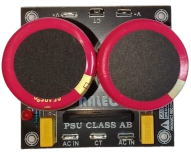
The PSU 2 Elco is a compact and efficient power supply unit designed for use in electronic circuits requiring stable DC voltage. It features two electrolytic capacitors (Elco) for enhanced filtering and voltage stabilization, making it ideal for powering sensitive components and circuits. This component is commonly used in audio amplifiers, microcontroller-based projects, and other low-power electronic devices.
Explore Projects Built with PSU 2 Elco
 Open Project in Cirkit Designer
 Open Project in Cirkit Designer
 Open Project in Cirkit Designer
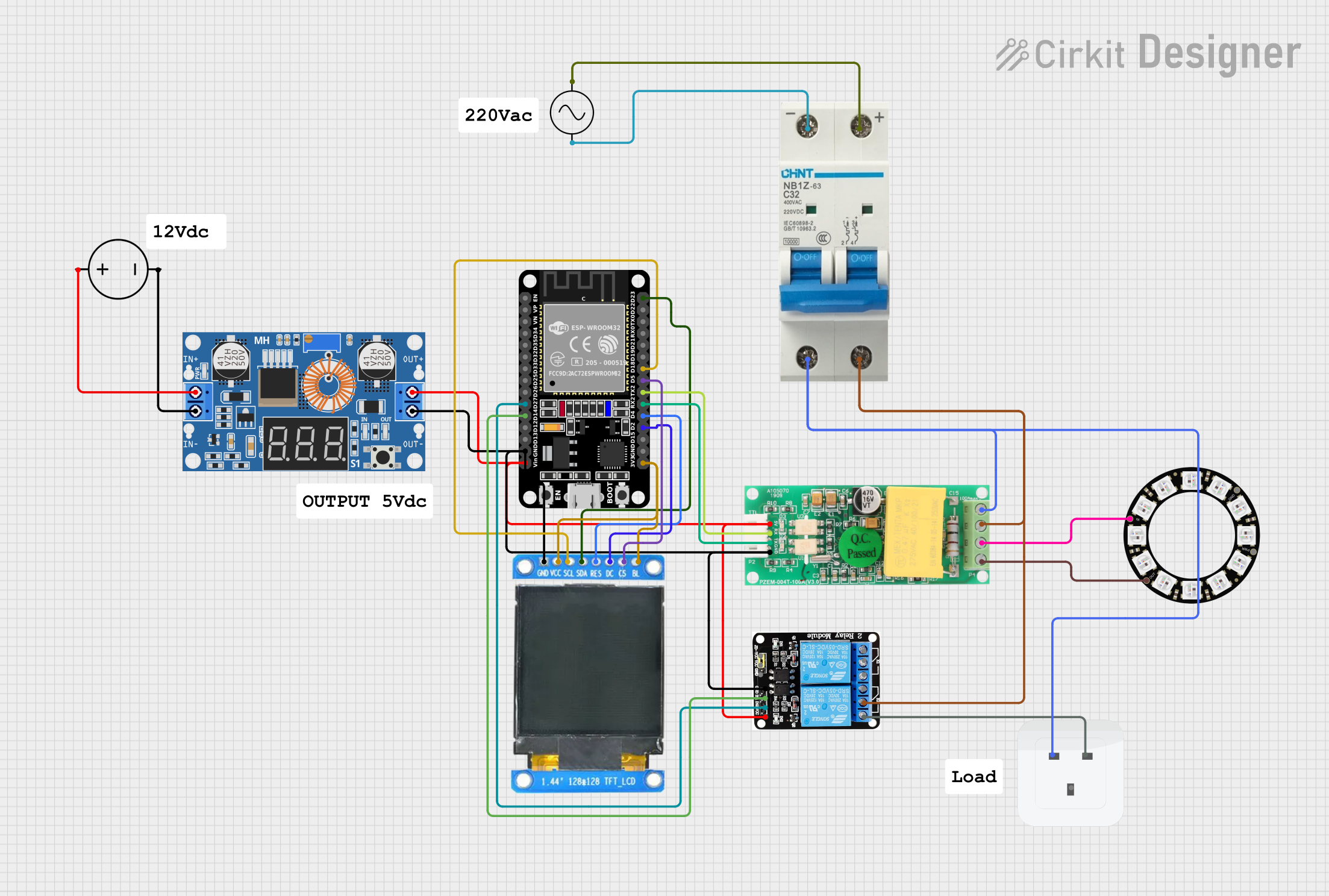
 Open Project in Cirkit Designer
Explore Projects Built with PSU 2 Elco

 Open Project in Cirkit Designer
 Open Project in Cirkit Designer
 Open Project in Cirkit Designer
 Open Project in Cirkit Designer
Common Applications and Use Cases
- Powering microcontroller boards (e.g., Arduino, Raspberry Pi)
- Audio amplifier circuits
- LED drivers and lighting systems
- General-purpose DC voltage regulation
- Prototyping and testing electronic circuits
Technical Specifications
The PSU 2 Elco is designed to provide stable DC output with minimal ripple. Below are its key technical specifications:
| Parameter | Value |
|---|---|
| Input Voltage Range | 6V to 24V AC or DC |
| Output Voltage Range | 5V to 12V DC (depending on design) |
| Maximum Output Current | 1A |
| Ripple Voltage | < 50mV |
| Capacitor Values | 2 x 1000µF (typical) |
| PCB Dimensions | 50mm x 30mm |
Pin Configuration and Descriptions
The PSU 2 Elco typically has the following pin configuration:
| Pin Name | Description |
|---|---|
| AC1 | AC input terminal 1 (for AC voltage input) |
| AC2 | AC input terminal 2 (for AC voltage input) |
| +V | Positive DC output terminal |
| GND | Ground (negative DC output terminal) |
Usage Instructions
How to Use the PSU 2 Elco in a Circuit
- Input Connection: Connect the AC1 and AC2 terminals to an AC voltage source (e.g., a transformer secondary winding). Alternatively, you can connect a DC voltage source to these terminals, observing polarity.
- Output Connection: Connect the +V terminal to the positive rail of your circuit and the GND terminal to the ground rail.
- Load Considerations: Ensure the connected load does not exceed the maximum output current of 1A.
- Filtering: The onboard electrolytic capacitors help reduce ripple voltage, but for highly sensitive circuits, you may add additional filtering capacitors at the output.
Important Considerations and Best Practices
- Input Voltage: Ensure the input voltage is within the specified range (6V to 24V). Exceeding this range may damage the component.
- Heat Dissipation: If the PSU 2 Elco is used near its maximum current rating, ensure adequate ventilation or heat sinking to prevent overheating.
- Polarity: When using a DC input, connect the positive terminal to AC1 and the negative terminal to AC2. Reversing polarity may damage the unit.
- Testing: Before connecting sensitive components, verify the output voltage using a multimeter.
Example: Using PSU 2 Elco with Arduino UNO
Below is an example of how to use the PSU 2 Elco to power an Arduino UNO:
- Connect a 12V AC transformer output to the AC1 and AC2 terminals of the PSU 2 Elco.
- Measure the output voltage at the +V and GND terminals to ensure it is 12V DC.
- Connect the +V terminal to the Arduino UNO's VIN pin and the GND terminal to the GND pin.
// Example Arduino code to blink an LED using power from PSU 2 Elco
// Ensure the PSU 2 Elco is providing a stable 12V DC to the Arduino UNO

int ledPin = 13; // Pin connected to the onboard LED

void setup() {
  pinMode(ledPin, OUTPUT); // Set the LED pin as an output
}

void loop() {
  digitalWrite(ledPin, HIGH); // Turn the LED on
  delay(1000);               // Wait for 1 second
  digitalWrite(ledPin, LOW);  // Turn the LED off
  delay(1000);               // Wait for 1 second
}
Troubleshooting and FAQs
Common Issues and Solutions
No Output Voltage:
- Check the input connections to ensure proper voltage is supplied.
- Verify that the input voltage is within the specified range (6V to 24V).
- Inspect the onboard components for visible damage (e.g., blown capacitors).
High Ripple Voltage:
- Ensure the input voltage source is stable and not fluctuating.
- Add additional filtering capacitors at the output if necessary.
Overheating:
- Reduce the load current if it exceeds 1A.
- Improve ventilation or add a heat sink to the PSU 2 Elco.
Incorrect Output Voltage:
- Verify the input voltage and ensure it matches the expected range.
- Check for faulty components, such as damaged capacitors or diodes.
FAQs
Q: Can I use the PSU 2 Elco with a DC input?
A: Yes, the PSU 2 Elco can accept a DC input. Connect the positive terminal to AC1 and the negative terminal to AC2.
Q: What happens if I exceed the maximum current rating?
A: Exceeding the 1A current rating may cause overheating, voltage drops, or damage to the PSU 2 Elco.
Q: Can I use the PSU 2 Elco to power a 5V device?
A: Yes, but you may need a voltage regulator (e.g., 7805) to step down the output voltage to 5V.
Q: How do I know if the onboard capacitors are damaged?
A: Damaged capacitors may appear swollen or leak electrolyte. You can also test them using a capacitance meter.