How to Use MB102: Examples, Pinouts, and Specs
Introduction
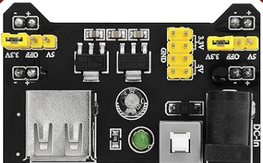
The MB102 is a breadboard power supply module designed to provide a convenient and reliable power source for electronic circuits built on a breadboard. It is widely used in prototyping and development due to its simplicity and versatility. The module typically offers dual voltage outputs of 5V and 3.3V, making it compatible with a wide range of components, sensors, and microcontrollers.
Explore Projects Built with MB102


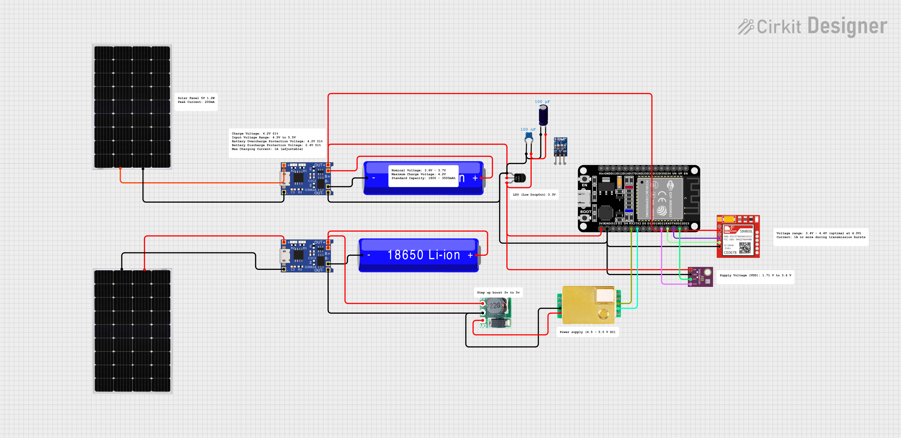
Explore Projects Built with MB102
Common Applications and Use Cases:
- Powering breadboard-based circuits during prototyping.
- Supplying regulated 5V or 3.3V to sensors, modules, and microcontrollers.
- Educational projects and DIY electronics.
- Testing and debugging small electronic circuits.
Technical Specifications
Below are the key technical details of the MB102 breadboard power supply module:
| Parameter | Specification |
|---|---|
| Input Voltage | 6.5V to 12V (via DC barrel jack) or 5V (via USB) |
| Output Voltage | 3.3V and 5V (selectable via jumpers) |
| Output Current | Up to 700mA (depending on input source) |
| Power Input Options | DC barrel jack or USB connector |
| Dimensions | 5.3cm x 3.5cm x 1.5cm |
| Compatibility | Standard 400-point and 830-point breadboards |
Pin Configuration and Descriptions
The MB102 module does not have traditional pins but instead connects directly to the power rails of a breadboard. Below is a description of its key components:
| Component | Description |
|---|---|
| DC Barrel Jack | Accepts 6.5V to 12V input for powering the module. |
| USB Connector | Provides an alternative 5V input source. |
| Voltage Selection Jumpers | Allows selection between 3.3V and 5V for each power rail. |
| Power Rails | Outputs regulated 3.3V or 5V to the breadboard's power rails. |
| Power Switch | Turns the module on or off. |
| LED Indicator | Lights up when the module is powered on. |
Usage Instructions
How to Use the MB102 in a Circuit:
Connect the Module to a Breadboard:
- Align the MB102 module with the power rails of your breadboard and insert it securely.
- Ensure the module fits properly into the breadboard without bending any pins.
Provide Power to the Module:
- Use a DC adapter (6.5V to 12V) to connect to the barrel jack, or use a USB cable to supply 5V via the USB connector.
Select the Desired Output Voltage:
- Use the jumpers on the module to set the output voltage for each power rail (3.3V or 5V).
Power On the Module:
- Flip the power switch to the "ON" position. The LED indicator will light up, confirming the module is powered.
Connect Your Circuit:
- Use the breadboard's power rails to distribute the regulated voltage to your components and modules.
Important Considerations and Best Practices:
- Input Voltage Range: Ensure the input voltage is within the specified range (6.5V to 12V for the barrel jack or 5V for USB). Exceeding this range may damage the module.
- Current Limitations: The module can supply up to 700mA, but this depends on the input source. Avoid overloading the module to prevent overheating.
- Voltage Selection: Double-check the jumper settings before connecting your circuit to avoid supplying the wrong voltage to your components.
- Heat Management: If the module becomes excessively hot, reduce the load or check for short circuits in your circuit.
Example: Using MB102 with an Arduino UNO
The MB102 can be used to power an Arduino UNO via the breadboard. Below is an example of how to connect and use it:
- Insert the MB102 into the breadboard and set the output voltage to 5V.
- Connect the breadboard's 5V power rail to the Arduino UNO's 5V pin.
- Connect the ground (GND) rail to the Arduino UNO's GND pin.
- Power the MB102 using a DC adapter or USB cable.
Here is a simple Arduino code example to blink an LED using the MB102 as the power source:
// Simple LED Blink Example
// Connect an LED to pin 13 of the Arduino UNO with a 220-ohm resistor.

void setup() {
  pinMode(13, OUTPUT); // Set pin 13 as an output pin
}

void loop() {
  digitalWrite(13, HIGH); // Turn the LED on
  delay(1000);            // Wait for 1 second
  digitalWrite(13, LOW);  // Turn the LED off
  delay(1000);            // Wait for 1 second
}
Troubleshooting and FAQs
Common Issues and Solutions:
Module Does Not Power On:
- Check the input voltage and ensure it is within the specified range.
- Verify that the power switch is in the "ON" position.
- Inspect the connections to the breadboard for proper alignment.
Incorrect Output Voltage:
- Ensure the jumpers are set correctly for the desired voltage (3.3V or 5V).
- Measure the output voltage with a multimeter to confirm the settings.
Overheating:
- Reduce the load on the module by disconnecting some components.
- Check for short circuits or excessive current draw in your circuit.
LED Indicator Not Lit:
- Verify the input power source is functioning correctly.
- Inspect the module for physical damage or loose connections.
FAQs:
Q: Can I use the MB102 to power a Raspberry Pi?
A: The MB102 is not recommended for powering a Raspberry Pi, as it may not provide sufficient current for stable operation. Use a dedicated power supply for the Raspberry Pi.
Q: Can I use both the USB and DC barrel jack inputs simultaneously?
A: No, only one input source should be used at a time to avoid damaging the module.
Q: What is the maximum current the MB102 can supply?
A: The module can supply up to 700mA, but this depends on the input source and load conditions.
Q: Is the MB102 compatible with all breadboards?
A: The MB102 is designed for standard 400-point and 830-point breadboards. Ensure your breadboard is compatible before use.