How to Use WSH231: Examples, Pinouts, and Specs
Introduction
The WSH231 is a surface mount resistor designed for use in electronic circuits. It is primarily utilized for current limiting, voltage division, and signal conditioning. Known for its compact size and high reliability, the WSH231 is a popular choice in modern electronic designs where space-saving and precision are critical.
Explore Projects Built with WSH231

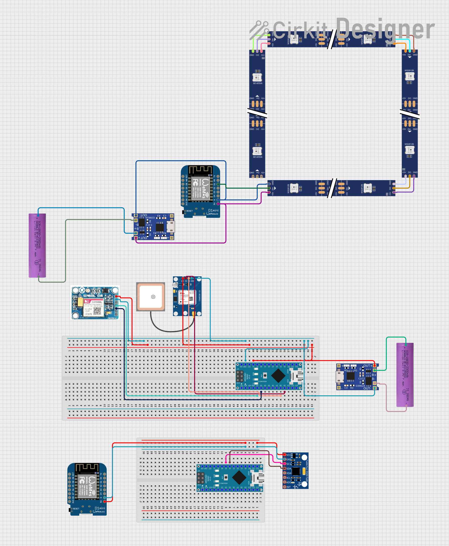
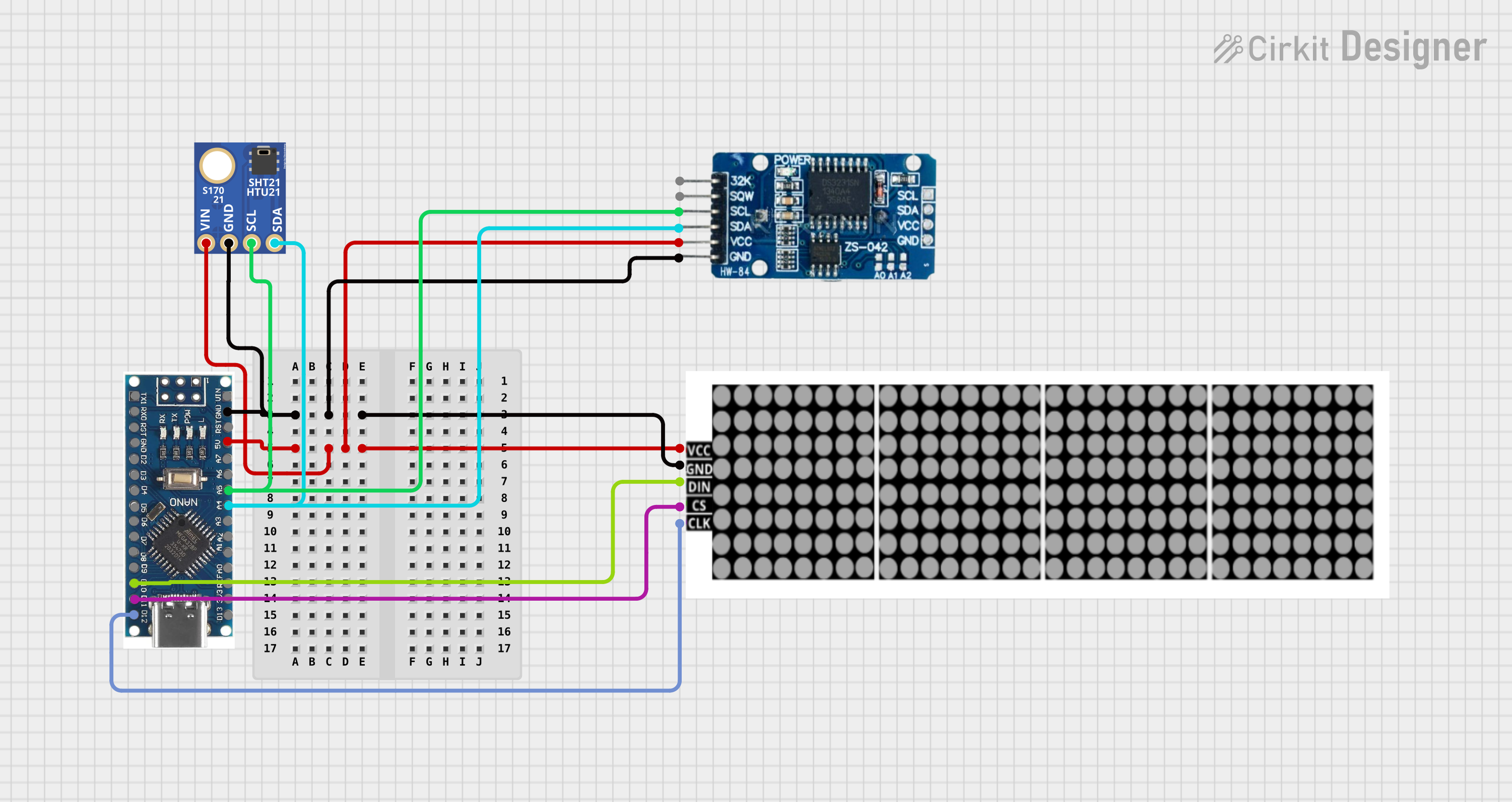

Explore Projects Built with WSH231
Common Applications
- Current limiting in LED circuits
- Voltage division in analog and digital circuits
- Signal conditioning in sensor interfaces
- Pull-up or pull-down resistors in microcontroller circuits
- General-purpose resistance in compact electronic devices
Technical Specifications
The WSH231 is available in various resistance values and tolerances, making it versatile for a wide range of applications. Below are the key technical details:
General Specifications
| Parameter | Value |
|---|---|
| Resistance Range | 1 Ω to 1 MΩ |
| Tolerance | ±1%, ±5% |
| Power Rating | 0.125 W (1/8 W) |
| Temperature Coefficient | ±100 ppm/°C |
| Operating Temperature | -55°C to +155°C |
| Package Type | 0805 (Surface Mount) |
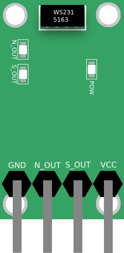
Pin Configuration and Description
The WSH231 is a two-terminal component with no polarity. Below is the pin description:
| Pin Number | Description |
|---|---|
| 1 | Resistor terminal (no polarity) |
| 2 | Resistor terminal (no polarity) |
Usage Instructions
How to Use the WSH231 in a Circuit
- Determine the Required Resistance Value: Select the appropriate resistance value based on your circuit's requirements for current limiting, voltage division, or other applications.
- Soldering: The WSH231 is a surface mount device (SMD). Use a soldering iron or reflow soldering process to attach the resistor to the PCB pads.
- Verify Connections: Ensure that the resistor is properly soldered and that there are no cold solder joints or shorts.
- Test the Circuit: Power on the circuit and measure the voltage or current to confirm the resistor is functioning as intended.
Important Considerations
- Power Dissipation: Ensure the resistor's power rating (0.125 W) is not exceeded. Calculate power dissipation using ( P = I^2R ) or ( P = V^2/R ).
- Temperature Effects: Be mindful of the temperature coefficient, especially in high-temperature environments, as resistance may vary slightly with temperature changes.
- Placement: Place the resistor close to the components it interacts with to minimize noise and parasitic effects.
Example: Using WSH231 with an Arduino UNO
The WSH231 can be used as a current-limiting resistor for an LED connected to an Arduino UNO. Below is an example circuit and code:
Circuit Description
- Connect one terminal of the WSH231 (e.g., 220 Ω) to the Arduino's digital pin (e.g., pin 13).
- Connect the other terminal of the WSH231 to the anode of the LED.
- Connect the cathode of the LED to the Arduino's GND.
Arduino Code
// Example code to blink an LED using WSH231 as a current-limiting resistor

const int ledPin = 13; // Pin connected to the LED through WSH231 resistor

void setup() {
  pinMode(ledPin, OUTPUT); // Set the LED pin as an output
}

void loop() {
  digitalWrite(ledPin, HIGH); // Turn the LED on
  delay(1000);               // Wait for 1 second
  digitalWrite(ledPin, LOW);  // Turn the LED off
  delay(1000);               // Wait for 1 second
}
Troubleshooting and FAQs
Common Issues
Resistor Overheating:
- Cause: Exceeding the power rating of the resistor.
- Solution: Verify the power dissipation using ( P = I^2R ) or ( P = V^2/R ). Use a resistor with a higher power rating if necessary.
Incorrect Resistance Value:
- Cause: Using the wrong resistor value for the application.
- Solution: Double-check the resistance value and tolerance before soldering.
Cold Solder Joints:
- Cause: Improper soldering technique.
- Solution: Re-solder the joints using proper heat and soldering tools.
Circuit Not Functioning as Expected:
- Cause: Misplacement or incorrect orientation of the resistor.
- Solution: Verify the resistor's placement and ensure it is connected to the correct pads.
FAQs
Q1: Can the WSH231 be used in high-frequency circuits?
A1: Yes, the WSH231 can be used in high-frequency circuits, but ensure proper placement to minimize parasitic inductance and capacitance.
Q2: What is the maximum voltage the WSH231 can handle?
A2: The maximum voltage depends on the power rating and resistance value. Use ( V = \sqrt{P \times R} ) to calculate the maximum voltage.
Q3: Can I use the WSH231 in a high-temperature environment?
A3: Yes, the WSH231 operates reliably up to +155°C. However, consider the temperature coefficient and ensure the resistor is not exposed to temperatures beyond its rating.
Q4: How do I identify the resistance value of the WSH231?
A4: The resistance value is typically marked on the resistor body using a 3- or 4-digit code. Refer to the SMD resistor code chart for decoding.
By following this documentation, you can effectively integrate the WSH231 into your electronic designs and troubleshoot any issues that arise.