Cirkit Designer Logo
Cirkit Designer
Your all-in-one circuit design IDE
Home / 
Component Documentation

How to Use LM2596: Examples, Pinouts, and Specs

Image of LM2596
Cirkit Designer LogoDesign with LM2596 in Cirkit Designer

Introduction

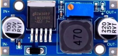
The LM2596 is a step-down (buck) voltage regulator designed to efficiently convert a higher input voltage into a stable, regulated output voltage. Manufactured by Arduino under the part ID "Nano," this component is capable of delivering up to 3A of output current. Its wide input voltage range and high efficiency make it ideal for use in power supply circuits, battery chargers, and embedded systems.

Explore Projects Built with LM2596

Use Cirkit Designer to design, explore, and prototype these projects online. Some projects support real-time simulation. Click "Open Project" to start designing instantly!
ESP32-Based Solar-Powered Current Monitoring System with OLED Display
Image of Solar Tracker and Monitoring System: A project utilizing LM2596 in a practical application
This circuit features an ESP32 microcontroller interfaced with a 0.96" OLED display, multiple LDR sensors with voltage dividers, an ACS712 current sensor, and two servomotors. The ESP32 reads analog values from the LDRs and the current sensor, and controls the servomotors. The LM2596 module steps down voltage for the circuit, which is powered by a combination of a solar panel and a 12V battery, with the current sensor monitoring the load current.
Cirkit Designer LogoOpen Project in Cirkit Designer
Arduino Nano Based GPS Tracker with GSM Communication and Accelerometer
Image of Circuit Aayush: A project utilizing LM2596 in a practical application
This circuit is designed for communication and location tracking purposes. It features an Arduino Nano interfaced with a SIM800L GSM module for cellular connectivity, a GPS NEO 6M module for obtaining geographical coordinates, and an AITrip ADXL335 GY-61 accelerometer for motion sensing. The LM2596 Step Down Module is used to regulate the power supply to the components.
Cirkit Designer LogoOpen Project in Cirkit Designer
Arduino GSM Security System with Motion Detection and Light Sensing
Image of Smart Home Security: A project utilizing LM2596 in a practical application
This circuit is designed to interface an Arduino UNO with a SIM800L GSM module, PIR sensor, photocell, buzzer, and multiple LEDs. It is likely intended for environmental monitoring and alerting, with the capability to communicate over GSM for remote notifications. The LM2596 module provides voltage regulation for the GSM module.
Cirkit Designer LogoOpen Project in Cirkit Designer
ESP8266 and SIM800L Based GPS Tracker with I2C LCD Display and Battery Power
Image of Little Innovator Competition: A project utilizing LM2596 in a practical application
This circuit integrates an ESP8266 NodeMCU microcontroller with a SIM800L GSM module, a GPS NEO 6M module, and a 16x2 I2C LCD display for communication and location tracking. It also includes a pushbutton for user input, a piezo buzzer for audio alerts, and is powered by a 2x 18650 battery pack through an LM2596 step-down module.
Cirkit Designer LogoOpen Project in Cirkit Designer

Explore Projects Built with LM2596

Use Cirkit Designer to design, explore, and prototype these projects online. Some projects support real-time simulation. Click "Open Project" to start designing instantly!
Image of Solar Tracker and Monitoring System: A project utilizing LM2596 in a practical application
ESP32-Based Solar-Powered Current Monitoring System with OLED Display
This circuit features an ESP32 microcontroller interfaced with a 0.96" OLED display, multiple LDR sensors with voltage dividers, an ACS712 current sensor, and two servomotors. The ESP32 reads analog values from the LDRs and the current sensor, and controls the servomotors. The LM2596 module steps down voltage for the circuit, which is powered by a combination of a solar panel and a 12V battery, with the current sensor monitoring the load current.
Cirkit Designer LogoOpen Project in Cirkit Designer
Image of Circuit Aayush: A project utilizing LM2596 in a practical application
Arduino Nano Based GPS Tracker with GSM Communication and Accelerometer
This circuit is designed for communication and location tracking purposes. It features an Arduino Nano interfaced with a SIM800L GSM module for cellular connectivity, a GPS NEO 6M module for obtaining geographical coordinates, and an AITrip ADXL335 GY-61 accelerometer for motion sensing. The LM2596 Step Down Module is used to regulate the power supply to the components.
Cirkit Designer LogoOpen Project in Cirkit Designer
Image of Smart Home Security: A project utilizing LM2596 in a practical application
Arduino GSM Security System with Motion Detection and Light Sensing
This circuit is designed to interface an Arduino UNO with a SIM800L GSM module, PIR sensor, photocell, buzzer, and multiple LEDs. It is likely intended for environmental monitoring and alerting, with the capability to communicate over GSM for remote notifications. The LM2596 module provides voltage regulation for the GSM module.
Cirkit Designer LogoOpen Project in Cirkit Designer
Image of Little Innovator Competition: A project utilizing LM2596 in a practical application
ESP8266 and SIM800L Based GPS Tracker with I2C LCD Display and Battery Power
This circuit integrates an ESP8266 NodeMCU microcontroller with a SIM800L GSM module, a GPS NEO 6M module, and a 16x2 I2C LCD display for communication and location tracking. It also includes a pushbutton for user input, a piezo buzzer for audio alerts, and is powered by a 2x 18650 battery pack through an LM2596 step-down module.
Cirkit Designer LogoOpen Project in Cirkit Designer

Common Applications

  • DC-DC power supply modules
  • Battery-powered devices
  • Voltage regulation for microcontrollers and sensors
  • LED drivers
  • Industrial automation systems

Technical Specifications

The LM2596 is a versatile and robust voltage regulator. Below are its key technical details:

General Specifications

Parameter Value
Input Voltage Range 4.5V to 40V
Output Voltage Range 1.23V to 37V (adjustable version)
Maximum Output Current 3A
Efficiency Up to 90%
Switching Frequency 150 kHz
Operating Temperature -40°C to +125°C

Pin Configuration

The LM2596 is typically available in a 5-pin TO-220 package. Below is the pinout description:

Pin Number Pin Name Description
1 VIN Input voltage pin. Connect to the unregulated DC input voltage.
2 Output Regulated output voltage pin. Connect to the load.
3 Ground Ground pin. Connect to the circuit ground.
4 Feedback Feedback pin. Used to set the output voltage via an external resistor divider.
5 ON/OFF Enable pin. Used to turn the regulator on or off.

Usage Instructions

The LM2596 is straightforward to use in a circuit. Below are the steps and considerations for proper usage:

Basic Circuit Design

  1. Input Capacitor: Place a capacitor (e.g., 100 µF) close to the VIN pin to stabilize the input voltage.
  2. Output Capacitor: Use a capacitor (e.g., 220 µF) at the output to reduce voltage ripple.
  3. Feedback Resistor Divider: Connect a resistor divider to the Feedback pin to set the desired output voltage. The output voltage is calculated using the formula: [ V_{OUT} = V_{REF} \times \left(1 + \frac{R1}{R2}\right) ] where ( V_{REF} ) is typically 1.23V.
  4. Inductor Selection: Choose an inductor with a suitable current rating (e.g., 33 µH) to ensure stable operation.

Example Circuit

Below is a typical application circuit for the LM2596:

VIN ----[Input Capacitor]----+----> LM2596 VIN
                             |
                            Load
                             |
GND -------------------------+----> LM2596 GND

Using LM2596 with Arduino UNO

The LM2596 can be used to power an Arduino UNO by stepping down a higher voltage (e.g., 12V) to 5V. Below is an example Arduino code to monitor the output voltage using an analog pin:

// LM2596 Output Voltage Monitoring with Arduino UNO
const int voltagePin = A0; // Connect LM2596 output to A0 via a voltage divider
const float referenceVoltage = 5.0; // Arduino UNO reference voltage
const float resistorRatio = 5.7; // Ratio of the resistor divider (e.g., R1 = 10k, R2 = 2.2k)

void setup() {
  Serial.begin(9600); // Initialize serial communication
}

void loop() {
  int analogValue = analogRead(voltagePin); // Read the analog pin
  float voltage = (analogValue / 1023.0) * referenceVoltage * resistorRatio;
  
  // Print the measured voltage to the Serial Monitor
  Serial.print("Output Voltage: ");
  Serial.print(voltage);
  Serial.println(" V");
  
  delay(1000); // Wait for 1 second before the next reading
}

Best Practices

  • Use low-ESR capacitors for better performance.
  • Ensure proper heat dissipation by using a heatsink if the regulator operates at high currents.
  • Avoid exceeding the maximum input voltage (40V) to prevent damage.
  • Use shielded inductors to minimize electromagnetic interference (EMI).

Troubleshooting and FAQs

Common Issues

  1. Output Voltage Not Stable

    • Cause: Insufficient input or output capacitance.
    • Solution: Add or replace capacitors with low-ESR types.
  2. Regulator Overheating

    • Cause: High current draw or inadequate heat dissipation.
    • Solution: Attach a heatsink to the LM2596 and ensure proper ventilation.
  3. No Output Voltage

    • Cause: Incorrect pin connections or damaged component.
    • Solution: Verify the wiring and check the input voltage.
  4. High Output Ripple

    • Cause: Poor capacitor selection or layout issues.
    • Solution: Use low-ESR capacitors and minimize trace lengths.

FAQs

Q: Can the LM2596 be used for 3.3V output?
A: Yes, the LM2596 adjustable version can be configured for a 3.3V output using the appropriate resistor divider.

Q: Is the LM2596 suitable for battery charging?
A: Yes, it can be used for battery charging applications, but additional circuitry may be required for proper charge control.

Q: What is the maximum current the LM2596 can handle?
A: The LM2596 can deliver up to 3A of output current, provided proper heat dissipation is ensured.

Q: Can I use the LM2596 with an Arduino Nano?
A: Yes, the LM2596 can step down a higher voltage to 5V or 3.3V to power an Arduino Nano.

By following this documentation, users can effectively integrate the LM2596 into their projects and troubleshoot common issues.