How to Use DHT11 Sensor Module: Examples, Pinouts, and Specs
Introduction
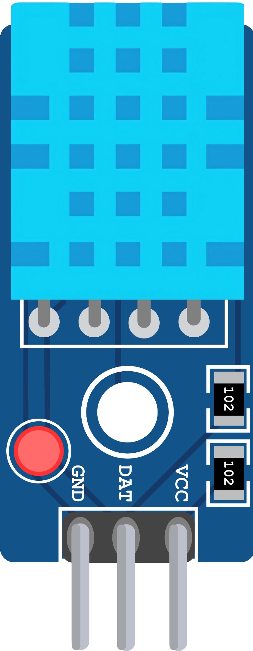
The DHT11 Sensor Module is a digital temperature and humidity sensor designed to provide accurate readings of environmental conditions. It features a calibrated digital signal output and uses a single-wire communication protocol, making it easy to interface with microcontrollers. The DHT11 is widely used in applications such as weather monitoring systems, home automation, and HVAC control.
Explore Projects Built with DHT11 Sensor Module
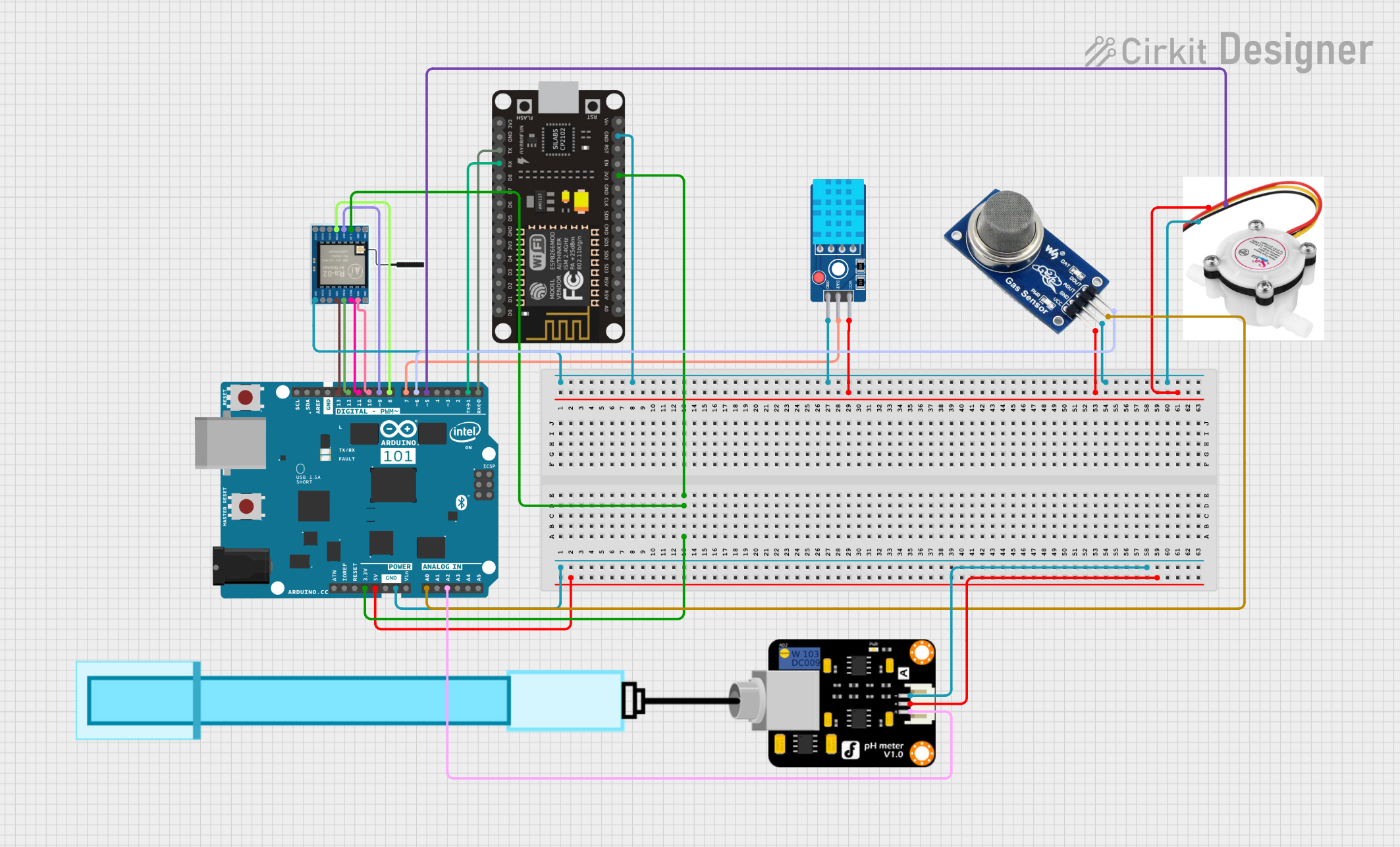
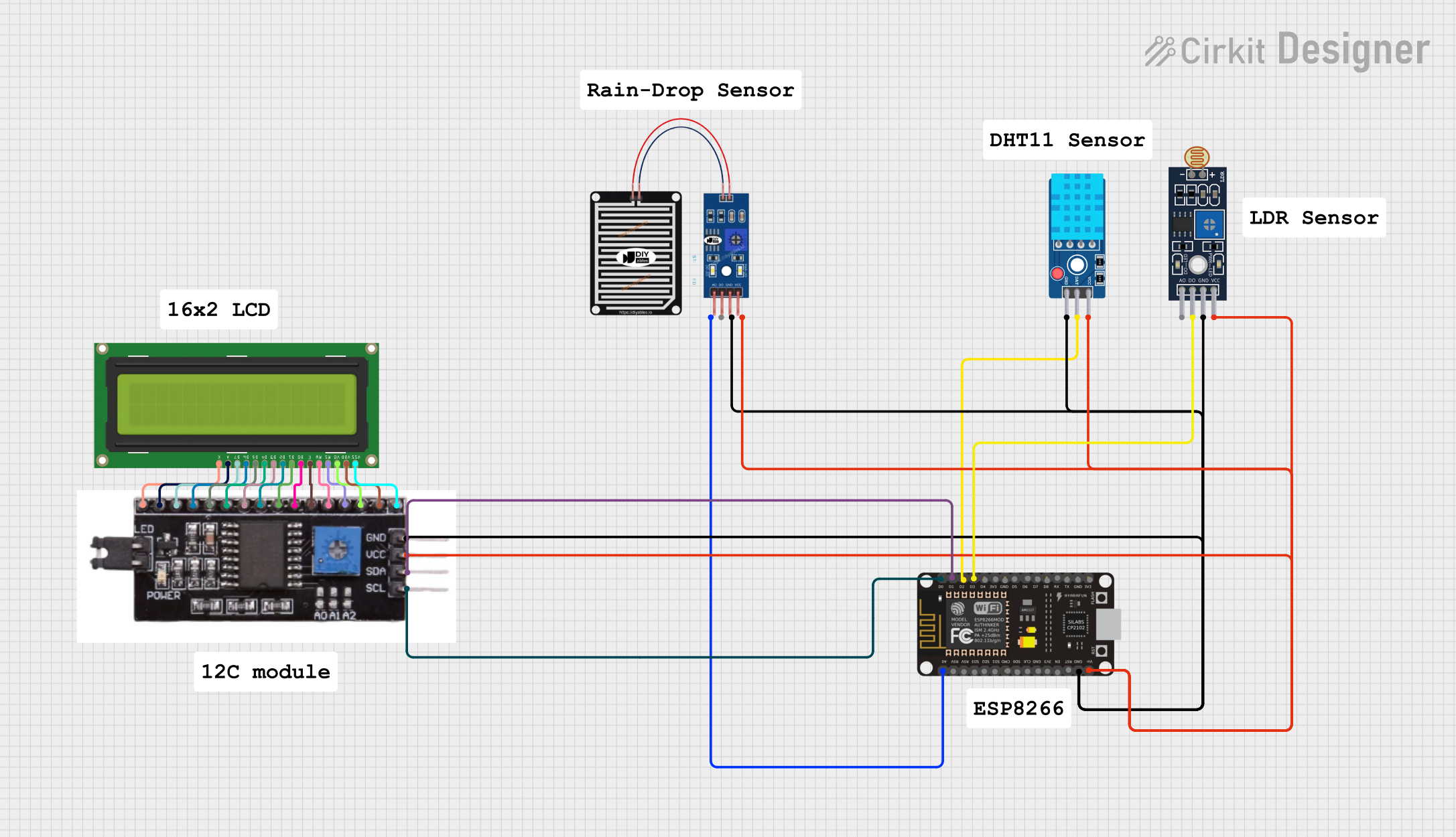
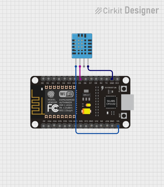

Explore Projects Built with DHT11 Sensor Module
Common Applications:
- Weather stations
- Home automation systems
- Greenhouse monitoring
- HVAC (Heating, Ventilation, and Air Conditioning) systems
- IoT (Internet of Things) projects
Technical Specifications
The DHT11 Sensor Module is a reliable and cost-effective solution for measuring temperature and humidity. Below are its key technical details:
Key Specifications:
| Parameter | Value |
|---|---|
| Operating Voltage | 3.3V to 5.5V |
| Operating Current | 0.3mA (measuring), 60µA (standby) |
| Temperature Range | 0°C to 50°C |
| Temperature Accuracy | ±2°C |
| Humidity Range | 20% to 90% RH |
| Humidity Accuracy | ±5% RH |
| Sampling Period | ≥ 1 second |
| Communication Protocol | Single-wire (digital) |
Pin Configuration:
The DHT11 Sensor Module typically has three or four pins. Below is the pinout description:
| Pin Number | Pin Name | Description |
|---|---|---|
| 1 | VCC | Power supply (3.3V to 5.5V) |
| 2 | DATA | Digital data output (connect to microcontroller) |
| 3 | NC (or GND) | Not connected (or Ground in some modules) |
| 4 | GND | Ground (0V reference) |
Note: Some DHT11 modules may have only three pins (VCC, DATA, and GND). Always refer to the specific module's datasheet for accurate pin configuration.
Usage Instructions
The DHT11 Sensor Module is straightforward to use in a circuit. Below are the steps and best practices for integrating it into your project:
Connecting the DHT11 to a Microcontroller:
- Power the Sensor: Connect the VCC pin to a 3.3V or 5V power source and the GND pin to ground.
- Data Communication: Connect the DATA pin to a digital input pin on your microcontroller. Use a pull-up resistor (typically 10kΩ) between the DATA pin and VCC to ensure reliable communication.
- Timing Considerations: The DHT11 requires a minimum sampling period of 1 second. Avoid polling the sensor more frequently to prevent inaccurate readings.
Example: Using the DHT11 with Arduino UNO
Below is an example of how to interface the DHT11 Sensor Module with an Arduino UNO. This code uses the popular DHT library, which simplifies communication with the sensor.
Circuit Diagram:
- Connect the DHT11's VCC pin to the Arduino's 5V pin.
- Connect the GND pin to the Arduino's GND pin.
- Connect the DATA pin to digital pin 2 on the Arduino.
Arduino Code:
#include <DHT.h>

// Define the pin where the DHT11 is connected
#define DHTPIN 2  // Digital pin 2

// Define the type of DHT sensor
#define DHTTYPE DHT11

// Initialize the DHT sensor
DHT dht(DHTPIN, DHTTYPE);

void setup() {
  Serial.begin(9600);  // Start serial communication
  Serial.println("DHT11 Sensor Module Test");
  dht.begin();  // Initialize the DHT sensor
}

void loop() {
  delay(2000);  // Wait 2 seconds between readings

  // Read temperature and humidity
  float humidity = dht.readHumidity();
  float temperature = dht.readTemperature();

  // Check if the readings are valid
  if (isnan(humidity) || isnan(temperature)) {
    Serial.println("Failed to read from DHT sensor!");
    return;
  }

  // Print the results to the Serial Monitor
  Serial.print("Humidity: ");
  Serial.print(humidity);
  Serial.print(" %\t");
  Serial.print("Temperature: ");
  Serial.print(temperature);
  Serial.println(" °C");
}
Best Practices:
- Use a Pull-Up Resistor: Always use a pull-up resistor (10kΩ) on the DATA line to ensure stable communication.
- Avoid Long Cables: Keep the connection wires as short as possible to reduce signal degradation.
- Sampling Interval: Do not poll the sensor more frequently than once per second to avoid inaccurate readings.
- Environmental Conditions: Avoid exposing the sensor to extreme temperatures or humidity levels outside its specified range.
Troubleshooting and FAQs
Common Issues and Solutions:
No Data Output:
- Cause: Missing pull-up resistor on the DATA line.
- Solution: Add a 10kΩ pull-up resistor between the DATA pin and VCC.
Inaccurate Readings:
- Cause: Sampling the sensor too frequently.
- Solution: Ensure a delay of at least 1 second between consecutive readings.
"Failed to Read from DHT Sensor" Error:
- Cause: Loose connections or incorrect wiring.
- Solution: Double-check all connections and ensure the DATA pin is connected to the correct digital pin on the microcontroller.
Sensor Not Responding:
- Cause: Power supply issues or damaged sensor.
- Solution: Verify the power supply voltage (3.3V to 5.5V) and replace the sensor if necessary.
FAQs:
Q: Can the DHT11 measure negative temperatures?
A: No, the DHT11 can only measure temperatures in the range of 0°C to 50°C. For negative temperatures, consider using the DHT22 sensor.
Q: Can I use the DHT11 with a 3.3V microcontroller?
A: Yes, the DHT11 operates within a voltage range of 3.3V to 5.5V, making it compatible with 3.3V systems.
Q: How long is the sensor's response time?
A: The DHT11 has a response time of approximately 1 second, so it is not suitable for applications requiring real-time measurements.
Q: Is the DHT11 waterproof?
A: No, the DHT11 is not waterproof. For outdoor or high-humidity environments, consider using a waterproof sensor like the DS18B20.
By following this documentation, you can effectively integrate the DHT11 Sensor Module into your projects and troubleshoot common issues with ease.