Cirkit Designer Logo
Cirkit Designer
Your all-in-one circuit design IDE
Home / 
Component Documentation

How to Use Adafruit SPI Flash: Examples, Pinouts, and Specs

Image of Adafruit SPI Flash
Cirkit Designer LogoDesign with Adafruit SPI Flash in Cirkit Designer

Introduction

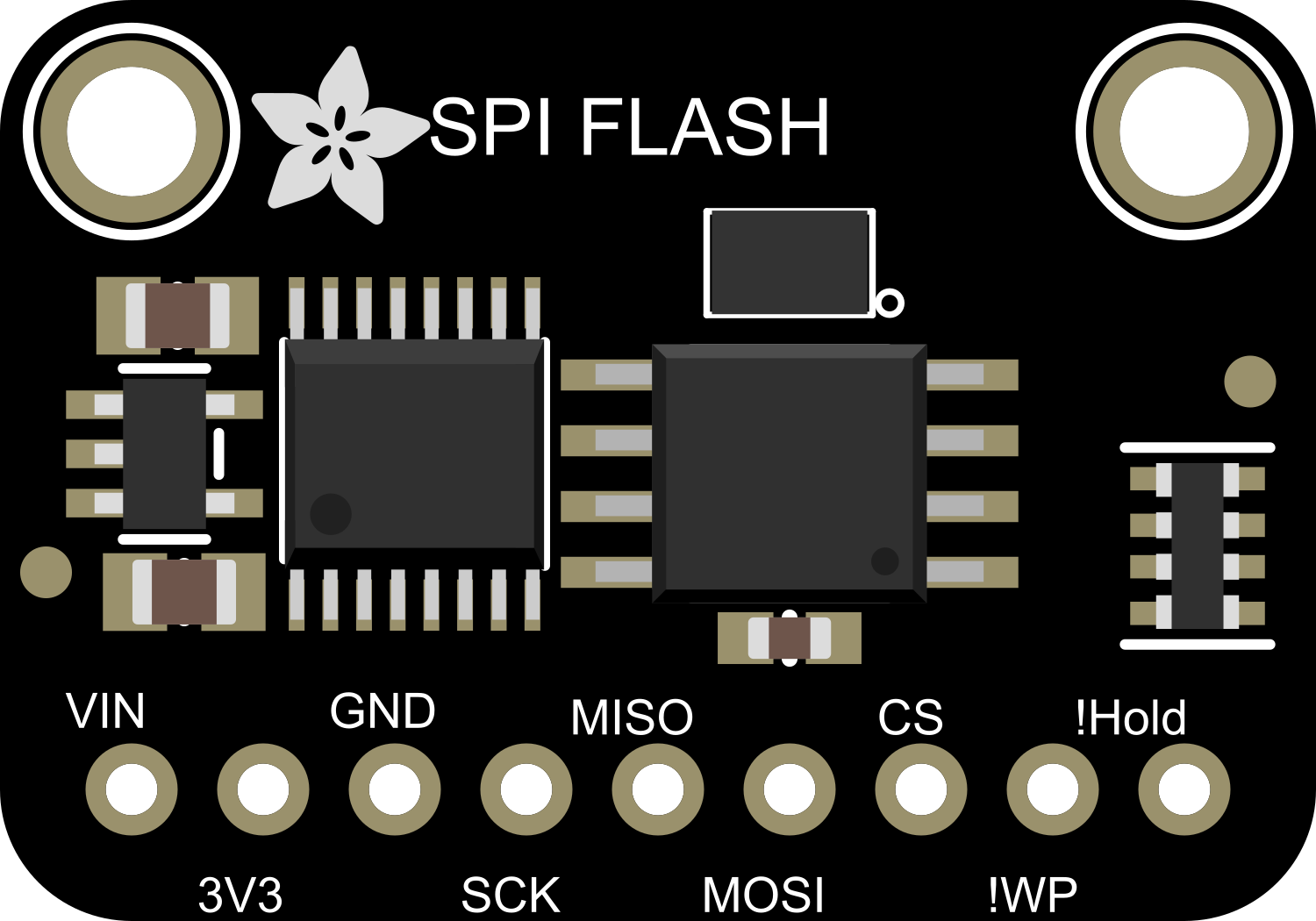
The Adafruit SPI Flash is a non-volatile memory module that provides 4MB of storage space. It operates over the Serial Peripheral Interface (SPI) protocol, which allows for fast data transfer rates and easy interfacing with microcontrollers such as the Arduino UNO. This component is ideal for applications that require data logging, firmware updates, or storing large amounts of data that exceed the internal memory capacity of the microcontroller.

Common applications include:

  • Data logging devices
  • Firmware storage for over-the-air updates
  • Storing audio, image, or other resource files for embedded systems
  • General-purpose non-volatile storage for embedded projects

Explore Projects Built with Adafruit SPI Flash

Use Cirkit Designer to design, explore, and prototype these projects online. Some projects support real-time simulation. Click "Open Project" to start designing instantly!
ESP32 and ADXL343-Based Battery-Powered Accelerometer with SPI Communication
Image of vibration module: A project utilizing Adafruit SPI Flash in a practical application
This circuit features an ESP32 microcontroller interfaced with an ADXL343 accelerometer via SPI communication, powered by a 12V battery regulated down to 5V and 8V using 7805 and 7808 voltage regulators. The ESP32 reads accelerometer data and outputs it via serial communication, with additional components including a pushbutton and a rocker switch for user input.
Cirkit Designer LogoOpen Project in Cirkit Designer
Battery-Powered Smart Sensor Hub with Adafruit QT Py RP2040
Image of wearable final: A project utilizing Adafruit SPI Flash in a practical application
This circuit features an Adafruit QT Py RP2040 microcontroller interfaced with an APDS9960 proximity sensor, an MPU6050 accelerometer and gyroscope, and an OLED display via I2C communication. It also includes a buzzer controlled by the microcontroller and is powered by a 3.7V LiPo battery with a toggle switch for power control.
Cirkit Designer LogoOpen Project in Cirkit Designer
Arduino UNO and ILI9341 Display-Based Interactive Game Console
Image of ILI9341 Sim Test - draw-line: A project utilizing Adafruit SPI Flash in a practical application
This circuit interfaces an Arduino UNO with an ILI9341 display module via SPI communication. The Arduino runs a game application, rendering graphics and handling user inputs to control game elements displayed on the ILI9341 screen.
Cirkit Designer LogoOpen Project in Cirkit Designer
Battery-Powered Smart Light with Proximity Sensor and OLED Display using Adafruit QT Py RP2040
Image of lab: A project utilizing Adafruit SPI Flash in a practical application
This circuit is a portable, battery-powered system featuring an Adafruit QT Py RP2040 microcontroller that interfaces with an OLED display, a proximity sensor, an accelerometer, and an RGB LED strip. The system is powered by a lithium-ion battery with a step-up boost converter to provide 5V for the LED strip, and it includes a toggle switch for power control. The microcontroller communicates with the sensors and display via I2C.
Cirkit Designer LogoOpen Project in Cirkit Designer

Explore Projects Built with Adafruit SPI Flash

Use Cirkit Designer to design, explore, and prototype these projects online. Some projects support real-time simulation. Click "Open Project" to start designing instantly!
Image of vibration module: A project utilizing Adafruit SPI Flash in a practical application
ESP32 and ADXL343-Based Battery-Powered Accelerometer with SPI Communication
This circuit features an ESP32 microcontroller interfaced with an ADXL343 accelerometer via SPI communication, powered by a 12V battery regulated down to 5V and 8V using 7805 and 7808 voltage regulators. The ESP32 reads accelerometer data and outputs it via serial communication, with additional components including a pushbutton and a rocker switch for user input.
Cirkit Designer LogoOpen Project in Cirkit Designer
Image of wearable final: A project utilizing Adafruit SPI Flash in a practical application
Battery-Powered Smart Sensor Hub with Adafruit QT Py RP2040
This circuit features an Adafruit QT Py RP2040 microcontroller interfaced with an APDS9960 proximity sensor, an MPU6050 accelerometer and gyroscope, and an OLED display via I2C communication. It also includes a buzzer controlled by the microcontroller and is powered by a 3.7V LiPo battery with a toggle switch for power control.
Cirkit Designer LogoOpen Project in Cirkit Designer
Image of ILI9341 Sim Test - draw-line: A project utilizing Adafruit SPI Flash in a practical application
Arduino UNO and ILI9341 Display-Based Interactive Game Console
This circuit interfaces an Arduino UNO with an ILI9341 display module via SPI communication. The Arduino runs a game application, rendering graphics and handling user inputs to control game elements displayed on the ILI9341 screen.
Cirkit Designer LogoOpen Project in Cirkit Designer
Image of lab: A project utilizing Adafruit SPI Flash in a practical application
Battery-Powered Smart Light with Proximity Sensor and OLED Display using Adafruit QT Py RP2040
This circuit is a portable, battery-powered system featuring an Adafruit QT Py RP2040 microcontroller that interfaces with an OLED display, a proximity sensor, an accelerometer, and an RGB LED strip. The system is powered by a lithium-ion battery with a step-up boost converter to provide 5V for the LED strip, and it includes a toggle switch for power control. The microcontroller communicates with the sensors and display via I2C.
Cirkit Designer LogoOpen Project in Cirkit Designer

Technical Specifications

Key Technical Details

  • Storage Capacity: 4MB
  • Interface: SPI (Serial Peripheral Interface)
  • Operating Voltage: 2.7V to 3.6V
  • Maximum Clock Frequency: 104MHz
  • Operating Current: 4mA (typical active), 1µA (deep power-down mode)

Pin Configuration and Descriptions

Pin Number Name Description
1 CS Chip Select, active low
2 DI Data In, SPI MOSI (Master Out Slave In)
3 WP Write Protect, active low
4 GND Ground
5 DO Data Out, SPI MISO (Master In Slave Out)
6 CLK Clock, SPI clock input
7 HOLD Hold, active low
8 VCC Power supply (2.7V to 3.6V)

Usage Instructions

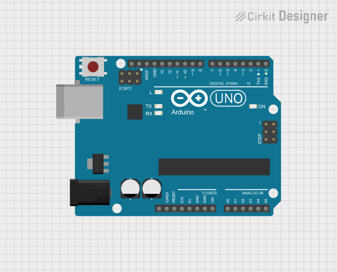
Interfacing with Arduino UNO

To use the Adafruit SPI Flash with an Arduino UNO, follow these steps:
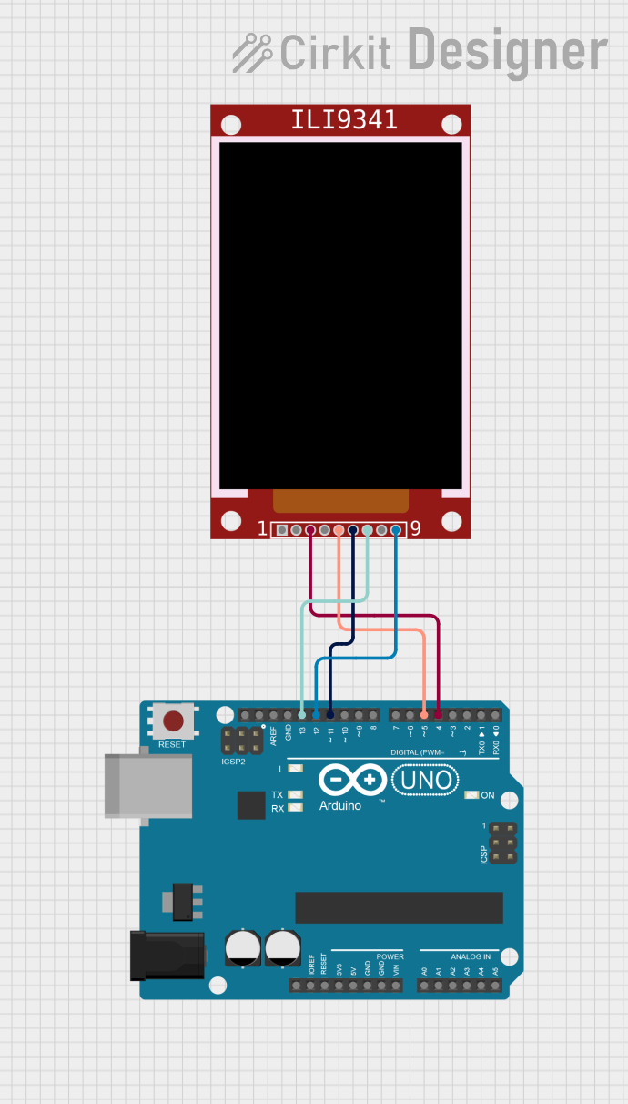
  1. Wiring:

    • Connect VCC to 3.3V on the Arduino UNO.
    • Connect GND to GND on the Arduino UNO.
    • Connect CS to a digital pin (e.g., D10) for chip select.
    • Connect DI to the MOSI pin (D11 on UNO).
    • Connect DO to the MISO pin (D12 on UNO).
    • Connect CLK to the SCK pin (D13 on UNO).
    • WP and HOLD can be connected to 3.3V if not used.
  2. Library Installation:

    • Install the Adafruit SPIFlash library via the Arduino Library Manager.
  3. Initialization:

    • Include the SPIFlash library in your sketch.
    • Create an object of the SPIFlash class and specify the chip select pin.
  4. Basic Operations:

    • Use the library functions to read, write, erase, and perform other operations on the flash memory.

Example Code

#include <SPI.h>
#include <Adafruit_SPIFlash.h>

// Create an SPI flash device object
Adafruit_SPIFlash flash = Adafruit_SPIFlash(10); // CS pin is 10

void setup() {
  Serial.begin(9600);
  // Initialize flash library and check if the flash chip is present
  if (!flash.begin()) {
    Serial.println("Error initializing SPI Flash chip!");
    while (1);
  }
  Serial.println("SPI Flash chip initialized successfully!");
}

void loop() {
  // Example operations: read, write, erase, etc.
}

Important Considerations and Best Practices

  • Ensure that the power supply voltage matches the operating voltage of the SPI Flash.
  • Use a level shifter if interfacing with a 5V microcontroller like the Arduino UNO.
  • Keep the SPI lines as short as possible to reduce noise and improve signal integrity.
  • Avoid running high-speed SPI lines near noisy components or circuits.

Troubleshooting and FAQs

Common Issues

  • Flash chip not recognized: Ensure that all connections are secure and the chip select pin is correctly defined in your code.
  • Data corruption: Verify the power supply stability and check for proper grounding.
  • Slow data transfer: Ensure that the SPI clock speed is set correctly and does not exceed the maximum frequency of the flash chip.

Solutions and Tips for Troubleshooting

  • Double-check wiring and solder joints for any loose connections or shorts.
  • Use serial debugging to print out status and error messages.
  • Make sure to use the correct SPI mode and clock divider for the flash chip.
  • Consult the Adafruit SPIFlash library documentation for additional functions and examples.

FAQs

Q: Can I use multiple SPI Flash chips with one Arduino? A: Yes, you can use multiple chips by assigning different chip select (CS) pins for each one.

Q: How do I protect specific sectors from being written or erased? A: The Adafruit SPIFlash library provides functions to enable or disable write protection on sectors.

Q: What is the lifespan of the SPI Flash memory? A: Flash memory typically has a finite number of write/erase cycles, often in the range of 100,000 cycles per sector.

Q: Can the Adafruit SPI Flash be used with other microcontrollers besides Arduino? A: Yes, as long as the microcontroller supports SPI communication and operates within the voltage range of the flash chip.