
How to Use Watt Meter AC: Examples, Pinouts, and Specs
 Design with Watt Meter AC in Cirkit Designer
Introduction
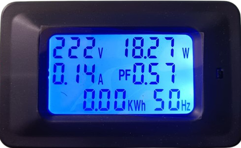
The Watt Meter AC is an electronic device designed to measure the power consumption of alternating current (AC) electrical devices. It provides real-time power readings in watts, enabling users to monitor energy usage and optimize power efficiency. This component is widely used in residential, commercial, and industrial applications to track energy consumption, identify power-hungry devices, and ensure compliance with energy-saving practices.
Explore Projects Built with Watt Meter AC
 Open Project in Cirkit Designer
 Open Project in Cirkit Designer
 Open Project in Cirkit Designer
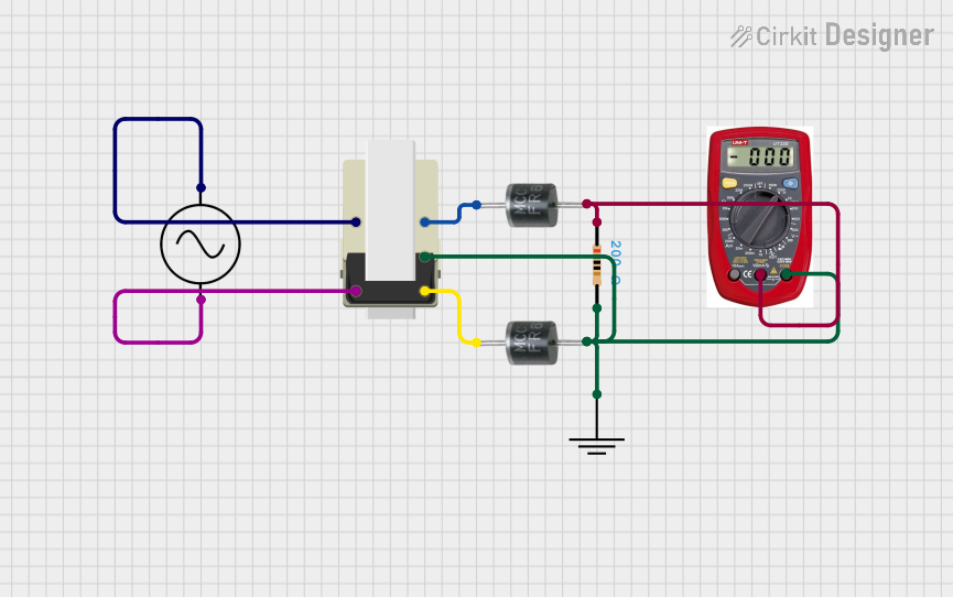 Open Project in Cirkit Designer
Explore Projects Built with Watt Meter AC
Open Project in Cirkit DesignerOpen Project in Cirkit DesignerOpen Project in Cirkit DesignerOpen Project in Cirkit DesignerCommon Applications and Use Cases
- Monitoring household appliances' power consumption.
- Evaluating the efficiency of electrical devices.
- Identifying energy-intensive equipment in industrial settings.
- Ensuring compliance with energy-saving regulations.
- Educational purposes for understanding power measurement.
Technical Specifications
The following table outlines the key technical details of the Watt Meter AC:
| Parameter | Specification |
|---|---|
| Input Voltage Range | 100V AC to 240V AC |
| Frequency Range | 50Hz to 60Hz |
| Power Measurement Range | 0.1W to 3680W (varies by model) |
| Accuracy | ±1% |
| Display Type | LCD/LED |
| Operating Temperature | -10°C to 50°C |
| Storage Temperature | -20°C to 70°C |
| Dimensions | Varies by model (e.g., 120mm x 70mm x 50mm) |
| Weight | Typically 150g to 300g |
Pin Configuration and Descriptions
For models with external connections (e.g., for integration with microcontrollers), the pin configuration is as follows:
| Pin | Name | Description |
|---|---|---|
| 1 | Live (L) | Connects to the live wire of the AC power source. |
| 2 | Neutral (N) | Connects to the neutral wire of the AC power source. |
| 3 | Ground (GND) | Provides grounding for safety and stability. |
| 4 | Data Out (Optional) | Outputs power data for external monitoring. |
Usage Instructions
How to Use the Watt Meter AC in a Circuit
- Safety First: Ensure the power source is turned off before connecting the Watt Meter AC.
- Wiring:
- Connect the live wire of the AC source to the "Live (L)" terminal of the watt meter.
- Connect the neutral wire of the AC source to the "Neutral (N)" terminal.
- If available, connect the ground wire to the "Ground (GND)" terminal.
- Power On: Turn on the AC power source. The watt meter will display the power consumption of the connected load in real-time.
- Optional Data Monitoring:
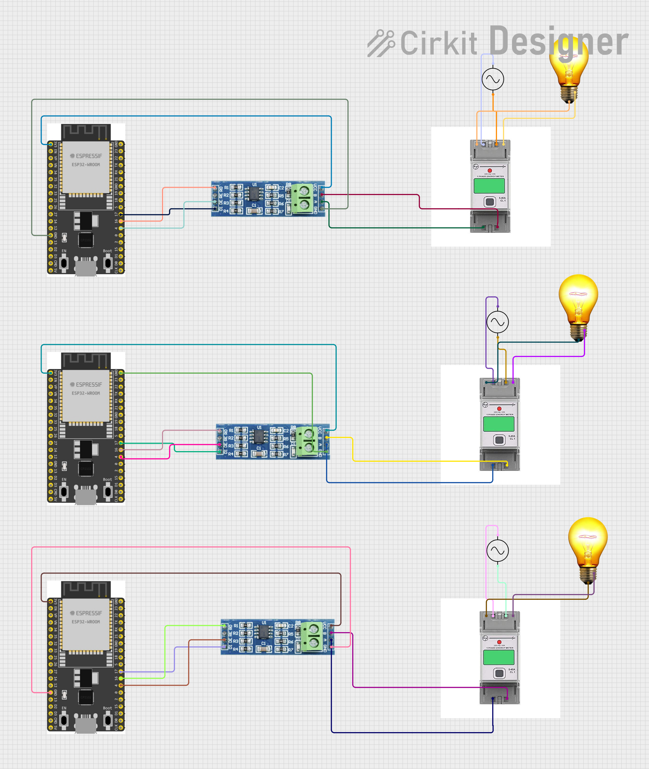
- If the watt meter includes a "Data Out" pin, connect it to a microcontroller (e.g., Arduino UNO) for external monitoring.
Important Considerations and Best Practices
- Voltage Compatibility: Ensure the watt meter's input voltage range matches your AC power source.
- Load Capacity: Do not exceed the maximum power measurement range of the watt meter.
- Grounding: Proper grounding is essential for safety and accurate measurements.
- Environmental Conditions: Avoid using the watt meter in extreme temperatures or humid environments.
- Calibration: Periodically calibrate the watt meter for optimal accuracy.
Example: Connecting to an Arduino UNO
If your watt meter supports data output, you can connect it to an Arduino UNO for real-time monitoring. Below is an example code snippet:
// Example code for reading data from a Watt Meter AC with a data output pin
// connected to an Arduino UNO. Ensure proper wiring before running this code.

#define DATA_PIN 2  // Pin connected to the watt meter's Data Out pin

void setup() {
  Serial.begin(9600);  // Initialize serial communication at 9600 baud
  pinMode(DATA_PIN, INPUT);  // Set the data pin as input
}

void loop() {
  int wattData = analogRead(DATA_PIN);  // Read data from the watt meter
  float power = wattData * (5.0 / 1023.0);  // Convert to voltage (example scaling)

  // Display the power reading in watts
  Serial.print("Power Consumption: ");
  Serial.print(power);
  Serial.println(" W");

  delay(1000);  // Wait for 1 second before the next reading
}
Note: The above code assumes the watt meter outputs an analog signal proportional to the power consumption. Refer to your watt meter's datasheet for specific details.
Troubleshooting and FAQs
Common Issues and Solutions
No Display or Power Reading:
- Cause: Incorrect wiring or no power supply.
- Solution: Double-check the wiring connections and ensure the AC power source is active.
Inaccurate Power Readings:
- Cause: Calibration drift or environmental interference.
- Solution: Recalibrate the watt meter and ensure it is used in a stable environment.
Overload Warning:
- Cause: Connected load exceeds the watt meter's maximum power range.
- Solution: Reduce the load to within the watt meter's specified range.
Data Output Not Working:
- Cause: Incorrect connection to the microcontroller or incompatible data format.
- Solution: Verify the wiring and consult the watt meter's datasheet for the correct data format.
FAQs
Q1: Can the Watt Meter AC measure DC power?
A1: No, the Watt Meter AC is specifically designed for alternating current (AC) power measurement. For DC power, use a DC watt meter.
Q2: Is it safe to use the watt meter outdoors?
A2: Most watt meters are designed for indoor use. If outdoor use is required, ensure the device is housed in a weatherproof enclosure.
Q3: How often should I calibrate the watt meter?
A3: Calibration frequency depends on usage. For regular use, calibrate every 6-12 months or as recommended by the manufacturer.
Q4: Can I use the watt meter with a generator?
A4: Yes, as long as the generator's output voltage and frequency fall within the watt meter's specifications.