
How to Use Modul LM2596: Examples, Pinouts, and Specs
 Design with Modul LM2596 in Cirkit Designer
Introduction
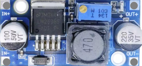
The LM2596 is a step-down (buck) voltage regulator designed to efficiently convert a higher input voltage into a stable, lower output voltage. It is widely used in power supply applications due to its high efficiency, compact size, and ability to handle loads of up to 3A. The module version of the LM2596 integrates additional components, such as input and output capacitors, an inductor, and a potentiometer, making it user-friendly and suitable for a variety of projects.
Explore Projects Built with Modul LM2596
 Open Project in Cirkit Designer
 Open Project in Cirkit Designer
 Open Project in Cirkit Designer
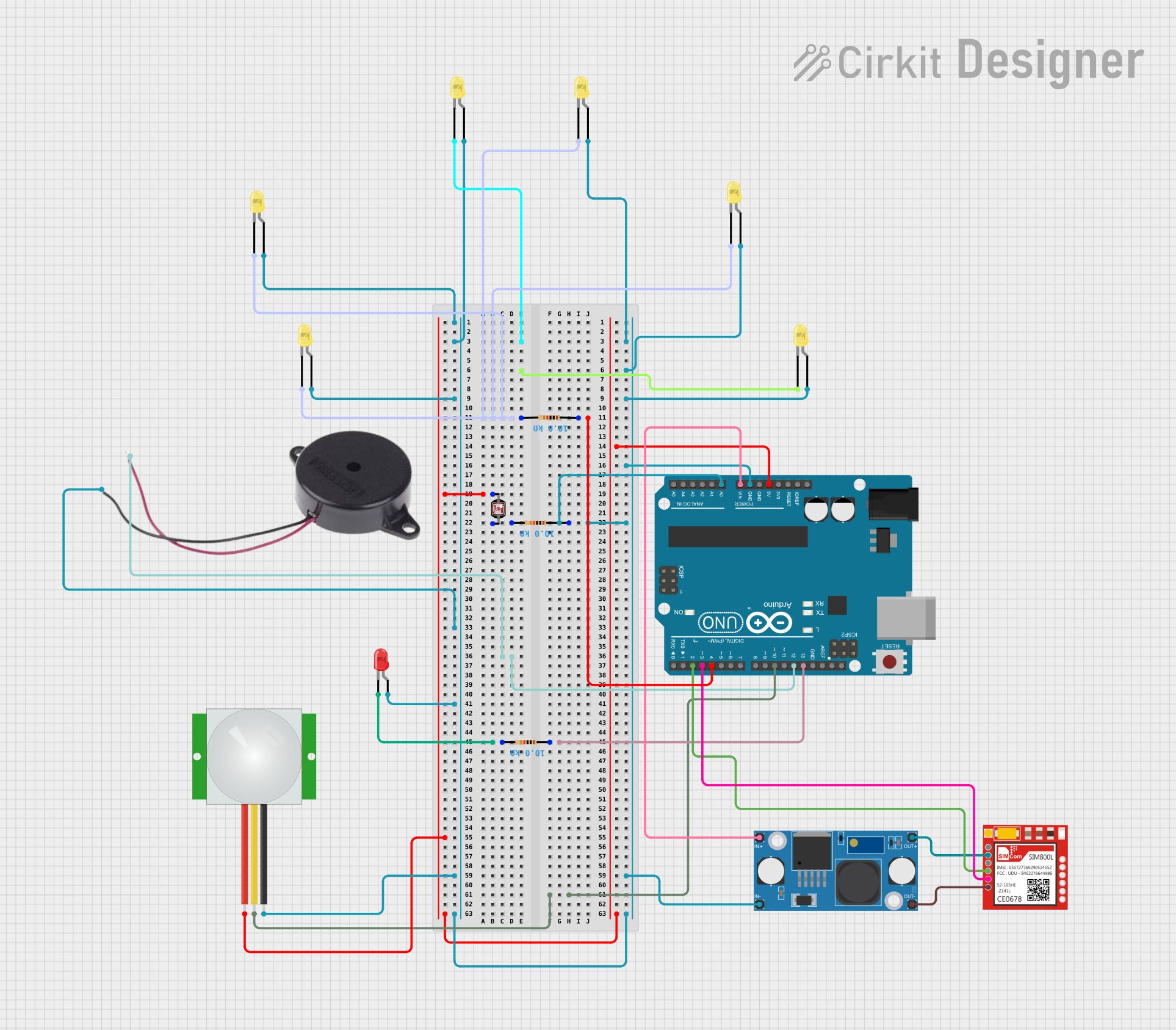 Open Project in Cirkit Designer
Explore Projects Built with Modul LM2596
Open Project in Cirkit DesignerOpen Project in Cirkit DesignerOpen Project in Cirkit DesignerOpen Project in Cirkit DesignerCommon Applications
- Powering microcontrollers and development boards (e.g., Arduino, Raspberry Pi)
- Battery-powered devices requiring regulated voltage
- LED drivers and lighting systems
- DIY electronics projects
- Industrial and automotive power supplies
Technical Specifications
Key Technical Details
| Parameter | Value |
|---|---|
| Input Voltage Range | 4.5V to 40V |
| Output Voltage Range | 1.23V to 37V (adjustable via potentiometer) |
| Maximum Output Current | 3A (with proper heat dissipation) |
| Efficiency | Up to 92% |
| Switching Frequency | 150 kHz |
| Operating Temperature | -40°C to +125°C |
| Dimensions (typical) | 45mm x 20mm x 14mm |
Pin Configuration and Descriptions
| Pin Name | Description |
|---|---|
| VIN | Input voltage pin. Connect the higher input voltage (4.5V to 40V). |
| GND | Ground pin. Connect to the ground of the circuit. |
| VOUT | Output voltage pin. Provides the regulated output voltage (1.23V to 37V). |
Usage Instructions
How to Use the LM2596 Module in a Circuit
Connect the Input Voltage (VIN):
- Attach the positive terminal of your power source to the
VINpin. - Connect the negative terminal of your power source to the
GNDpin.
- Attach the positive terminal of your power source to the
Adjust the Output Voltage:
- Use the onboard potentiometer to set the desired output voltage.
- Turn the potentiometer clockwise to increase the output voltage or counterclockwise to decrease it.
- Use a multimeter to measure the output voltage at the
VOUTpin while adjusting.
Connect the Load:
- Attach the positive terminal of your load to the
VOUTpin. - Connect the negative terminal of your load to the
GNDpin.
- Attach the positive terminal of your load to the
Verify Connections:
- Double-check all connections to ensure proper polarity and secure wiring.
Power On:
- Turn on the power source and verify the output voltage using a multimeter before connecting sensitive devices.
Important Considerations and Best Practices
- Heat Dissipation: The LM2596 module can handle up to 3A, but proper heat dissipation (e.g., a heatsink) is required for high current loads.
- Input Voltage: Ensure the input voltage is at least 1.5V higher than the desired output voltage for proper regulation.
- Capacitor Ratings: Use capacitors with appropriate voltage ratings to avoid damage.
- Avoid Overloading: Do not exceed the maximum current rating of 3A to prevent overheating or damage.
Example: Using LM2596 with Arduino UNO
The LM2596 module can be used to power an Arduino UNO by stepping down a 12V input to 5V. Below is an example circuit and Arduino code to blink an LED:
Circuit Connections
- Connect a 12V power source to the
VINandGNDpins of the LM2596 module. - Adjust the potentiometer to set the output voltage to 5V.
- Connect the
VOUTpin of the LM2596 to the5Vpin of the Arduino UNO. - Connect the
GNDpin of the LM2596 to theGNDpin of the Arduino UNO.
Arduino Code
// Simple LED Blink Example
// This code blinks an LED connected to pin 13 of the Arduino UNO.

void setup() {
  pinMode(13, OUTPUT); // Set pin 13 as an output pin
}

void loop() {
  digitalWrite(13, HIGH); // Turn the LED on
  delay(1000);            // Wait for 1 second
  digitalWrite(13, LOW);  // Turn the LED off
  delay(1000);            // Wait for 1 second
}
Troubleshooting and FAQs
Common Issues and Solutions
No Output Voltage:
- Cause: Incorrect wiring or insufficient input voltage.
- Solution: Verify all connections and ensure the input voltage is within the specified range.
Output Voltage Not Adjustable:
- Cause: Faulty potentiometer or incorrect adjustment.
- Solution: Turn the potentiometer slowly and check the output voltage with a multimeter.
Overheating:
- Cause: Excessive current draw or poor heat dissipation.
- Solution: Reduce the load current or attach a heatsink to the module.
Voltage Drop Under Load:
- Cause: Insufficient input voltage or overloaded module.
- Solution: Ensure the input voltage is at least 1.5V higher than the output voltage and reduce the load.
FAQs
Q1: Can the LM2596 module be used to charge batteries?
A1: Yes, but ensure the output voltage is set to the appropriate charging voltage for the battery type, and use additional circuitry for current limiting if required.
Q2: What is the maximum input voltage for the LM2596 module?
A2: The maximum input voltage is 40V. Exceeding this value may damage the module.
Q3: Can the LM2596 module provide a fixed output voltage?
A3: Yes, you can adjust the potentiometer to set a fixed output voltage. Once set, the module will maintain the output voltage as long as the input voltage and load are within specifications.
Q4: Is the LM2596 module suitable for audio applications?
A4: The LM2596 may introduce switching noise, which can affect audio circuits. Consider using additional filtering components if noise is an issue.