How to Use CD4026: Examples, Pinouts, and Specs
Introduction
The CD4026 is a decade counter and divider IC manufactured by NXP Semiconductors (Part ID: CD4026BNSR). It is designed to count from 0 to 9 and is widely used in digital electronics for applications requiring binary-coded decimal (BCD) outputs. The IC is particularly popular in digital clocks, frequency counters, and other numerical display systems. One of its key features is the ability to directly drive 7-segment displays, making it a versatile choice for projects involving numerical displays.
Explore Projects Built with CD4026

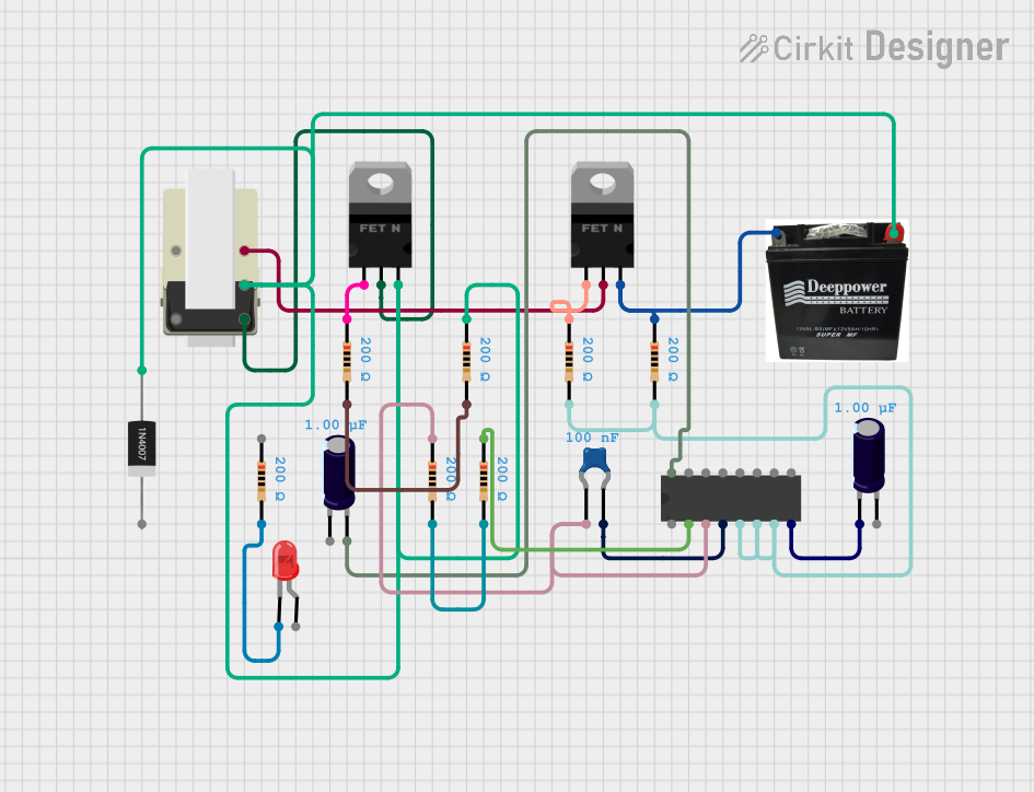

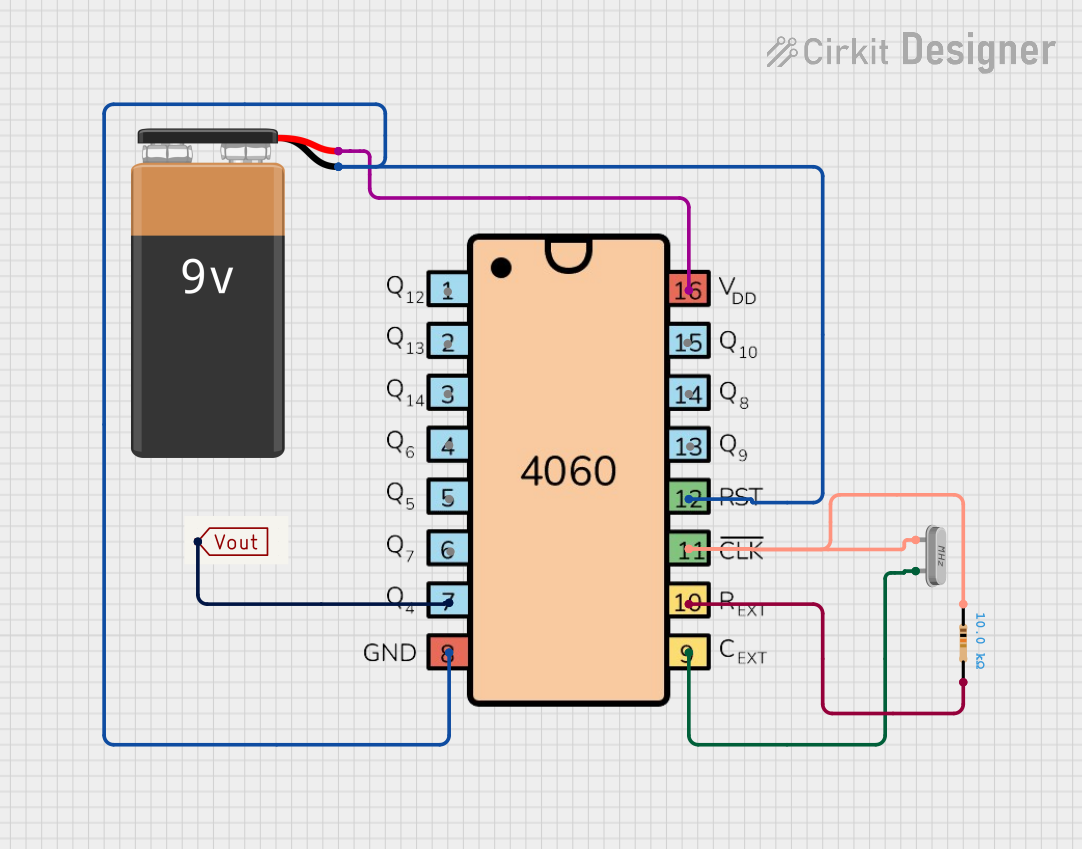
Explore Projects Built with CD4026
Common Applications
- Digital clocks
- Frequency counters
- Event counters
- Digital voltmeters
- Scoreboards
- Timer circuits
Technical Specifications
The following table outlines the key technical specifications of the CD4026:
| Parameter | Value |
|---|---|
| Supply Voltage (V(_{DD})) | 3V to 15V |
| Input Voltage Range | 0V to V(_{DD}) |
| Maximum Clock Frequency | 6 MHz (at V(_{DD}) = 10V) |
| Output Current (per pin) | ±1.5 mA |
| Power Dissipation | 500 mW |
| Operating Temperature Range | -55°C to +125°C |
| Package Type | SOIC-16, PDIP-16 |
Pin Configuration and Descriptions
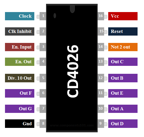
The CD4026 has 16 pins, each serving a specific function. The table below provides a detailed description of each pin:
| Pin Number | Pin Name | Description |
|---|---|---|
| 1 | Clock (CLK) | Input for clock pulses; increments the counter on the rising edge. |
| 2 | Enable (EN) | Enables or disables the clock input. Active HIGH. |
| 3 | Reset (RST) | Resets the counter to zero when HIGH. |
| 4 | Display Enable | Enables or disables the 7-segment display output. Active HIGH. |
| 5 | Segment b | Output for segment 'b' of the 7-segment display. |
| 6 | Segment c | Output for segment 'c' of the 7-segment display. |
| 7 | Unused | Not connected internally; leave floating or connect to ground. |
| 8 | Ground (GND) | Ground reference for the IC. |
| 9 | Segment d | Output for segment 'd' of the 7-segment display. |
| 10 | Segment e | Output for segment 'e' of the 7-segment display. |
| 11 | Segment f | Output for segment 'f' of the 7-segment display. |
| 12 | Segment g | Output for segment 'g' of the 7-segment display. |
| 13 | Segment a | Output for segment 'a' of the 7-segment display. |
| 14 | Carry Out (CO) | Outputs a carry signal for cascading multiple CD4026 ICs. |
| 15 | Common Cathode | Connects to the common cathode of the 7-segment display. |
| 16 | V(_{DD}) | Positive supply voltage. |
Usage Instructions
How to Use the CD4026 in a Circuit
- Power Supply: Connect pin 16 (V(_{DD})) to a positive voltage source (3V to 15V) and pin 8 (GND) to ground.
- Clock Input: Provide clock pulses to the CLK pin (pin 1). Each rising edge of the clock pulse increments the counter.
- Reset: To reset the counter to zero, apply a HIGH signal to the RST pin (pin 3).
- Display Enable: To enable the 7-segment display output, set the Display Enable pin (pin 4) HIGH.
- 7-Segment Display: Connect the segment output pins (pins 5, 6, 9, 10, 11, 12, and 13) to the corresponding segments of a 7-segment display.
- Cascading: For applications requiring counts beyond 9, use the Carry Out (CO) pin (pin 14) to cascade multiple CD4026 ICs.
Important Considerations
- Use current-limiting resistors (typically 330Ω to 1kΩ) between the segment output pins and the 7-segment display to prevent damage to the IC and display.
- Ensure the clock signal is clean and free of noise to avoid erratic counting.
- Avoid exceeding the maximum supply voltage (15V) to prevent permanent damage to the IC.
Example: Connecting CD4026 to an Arduino UNO
Below is an example of how to connect the CD4026 to an Arduino UNO to drive a 7-segment display:
Circuit Connections
- Connect the CD4026's V(_{DD}) (pin 16) to the Arduino's 5V pin.
- Connect GND (pin 8) to the Arduino's GND.
- Connect the CLK pin (pin 1) to Arduino digital pin 2.
- Connect the RST pin (pin 3) to Arduino digital pin 3.
- Connect the segment output pins (pins 5, 6, 9, 10, 11, 12, and 13) to the corresponding segments of the 7-segment display.
Arduino Code
// Define pin connections
const int clockPin = 2;  // Clock input to CD4026
const int resetPin = 3;  // Reset input to CD4026

void setup() {
  pinMode(clockPin, OUTPUT);  // Set clock pin as output
  pinMode(resetPin, OUTPUT);  // Set reset pin as output

  // Initialize pins
  digitalWrite(clockPin, LOW);
  digitalWrite(resetPin, LOW);
}

void loop() {
  // Reset the counter
  digitalWrite(resetPin, HIGH);  // Send HIGH signal to reset pin
  delay(10);                     // Short delay
  digitalWrite(resetPin, LOW);   // Set reset pin back to LOW

  // Increment the counter
  for (int i = 0; i < 10; i++) { // Loop to count from 0 to 9
    digitalWrite(clockPin, HIGH);  // Send HIGH signal to clock pin
    delay(500);                    // Wait for 500ms
    digitalWrite(clockPin, LOW);   // Set clock pin back to LOW
    delay(500);                    // Wait for 500ms
  }
}
Troubleshooting and FAQs
Common Issues and Solutions
The 7-segment display does not light up:
- Ensure the Display Enable pin (pin 4) is set HIGH.
- Check the connections between the segment output pins and the 7-segment display.
- Verify that current-limiting resistors are correctly installed.
Erratic counting:
- Ensure the clock signal is clean and free of noise.
- Use a debouncing circuit or software debouncing if the clock signal is generated by a mechanical switch.
The counter does not reset:
- Verify that the RST pin (pin 3) is receiving a HIGH signal to reset the counter.
- Check for loose or incorrect connections to the RST pin.
The IC overheats:
- Ensure the supply voltage does not exceed 15V.
- Verify that the current-limiting resistors are properly sized to limit current through the 7-segment display.
FAQs
Q: Can I cascade multiple CD4026 ICs for larger counts?
A: Yes, you can use the Carry Out (CO) pin (pin 14) to cascade multiple CD4026 ICs for counts beyond 9.
Q: What type of 7-segment display should I use with the CD4026?
A: The CD4026 is designed to work with common cathode 7-segment displays.
Q: Can the CD4026 operate at 3.3V?
A: Yes, the CD4026 can operate at supply voltages as low as 3V, making it compatible with 3.3V systems.