How to Use opamp: Examples, Pinouts, and Specs
Introduction
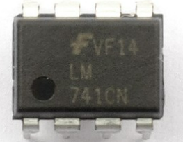
An operational amplifier (op-amp) is a high-gain voltage amplifier with a differential input and, usually, a single-ended output. Op-amps are fundamental building blocks in analog electronic circuits and are used in various signal processing applications, including filtering, amplification, and mathematical operations such as addition, subtraction, integration, and differentiation.
Explore Projects Built with opamp
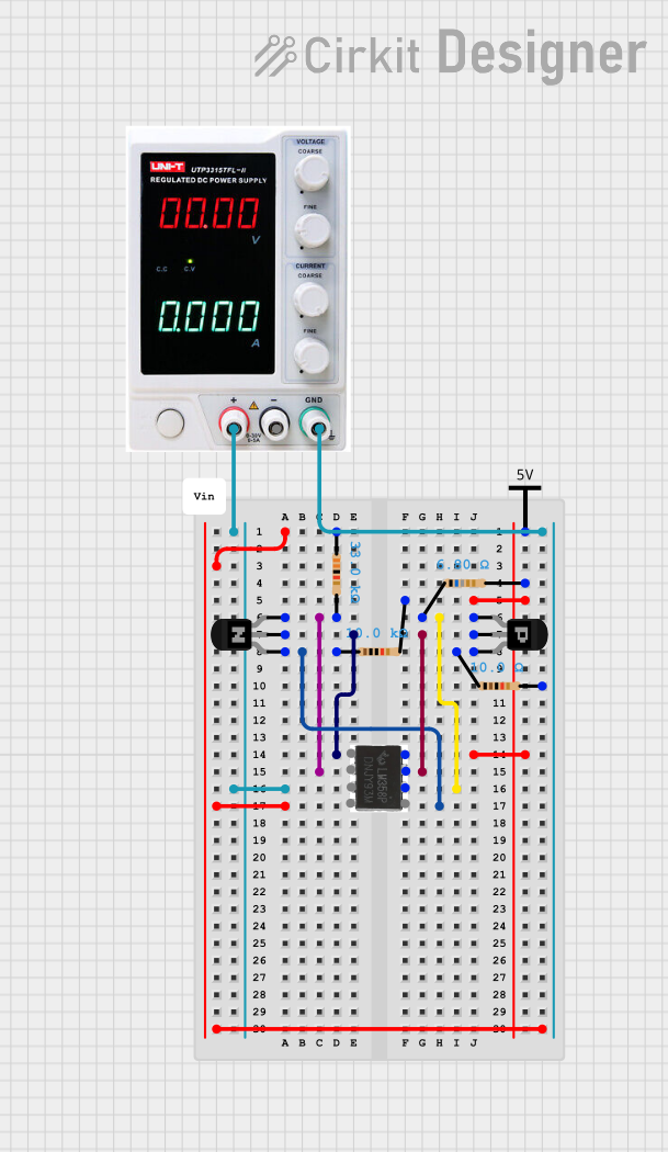
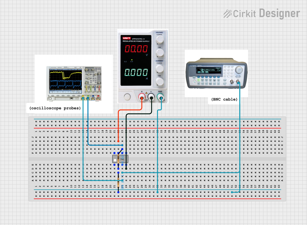
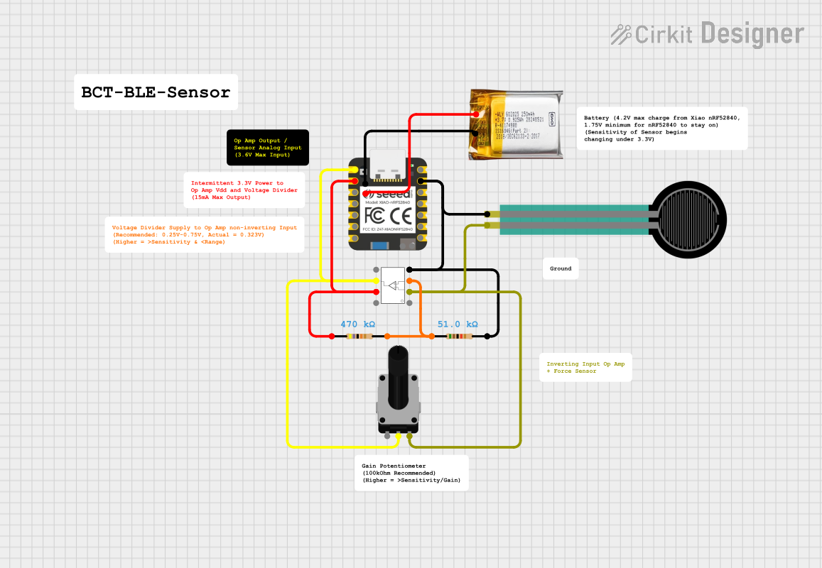
Explore Projects Built with opamp
Common Applications and Use Cases
- Signal Amplification: Amplifying weak signals in audio equipment, sensors, and instrumentation.
- Active Filters: Implementing low-pass, high-pass, band-pass, and band-stop filters.
- Oscillators: Generating waveforms in function generators and clock circuits.
- Comparators: Comparing two voltages and outputting a digital signal indicating which is higher.
- Mathematical Operations: Performing analog computations like addition, subtraction, integration, and differentiation.
Technical Specifications
Key Technical Details
| Parameter | Value |
|---|---|
| Supply Voltage | ±3V to ±18V |
| Input Offset Voltage | 2mV (typical) |
| Input Bias Current | 20nA (typical) |
| Input Impedance | 1MΩ to 10MΩ |
| Output Impedance | 75Ω |
| Gain Bandwidth Product | 1MHz to 10MHz |
| Slew Rate | 0.5V/µs to 20V/µs |
| Output Voltage Swing | ±(Vcc - 1.5V) |
| Common-Mode Rejection Ratio (CMRR) | 70dB to 120dB |
| Power Consumption | 0.5mW to 10mW |
Pin Configuration and Descriptions
| Pin Number | Pin Name | Description |
|---|---|---|
| 1 | Offset Null | Used for offset voltage adjustment (optional) |
| 2 | Inverting Input (V-) | Input for the inverting signal |
| 3 | Non-Inverting Input (V+) | Input for the non-inverting signal |
| 4 | V- (Negative Supply) | Negative power supply voltage |
| 5 | Offset Null | Used for offset voltage adjustment (optional) |
| 6 | Output | Output of the op-amp |
| 7 | V+ (Positive Supply) | Positive power supply voltage |
| 8 | NC (No Connection) | Not connected |
Usage Instructions
How to Use the Component in a Circuit
- Power Supply: Connect the positive supply voltage (V+) to pin 7 and the negative supply voltage (V-) to pin 4. Ensure the supply voltage is within the specified range.
- Input Signals: Connect the input signals to the inverting input (pin 2) and the non-inverting input (pin 3). The difference between these inputs will be amplified.
- Output Signal: The amplified output signal will be available at pin 6.
- Offset Null (Optional): If precise offset voltage adjustment is required, connect a potentiometer between pins 1 and 5, with the wiper connected to the negative supply voltage (V-).
Important Considerations and Best Practices
- Power Supply Decoupling: Use decoupling capacitors (e.g., 0.1µF) close to the power supply pins to reduce noise and improve stability.
- Input Impedance: Ensure the source impedance is low compared to the op-amp's input impedance to minimize signal loss.
- Feedback Network: Use appropriate feedback resistors and capacitors to set the desired gain and bandwidth.
- Thermal Management: Ensure proper thermal management to prevent overheating, especially in high-power applications.
Example Circuit: Non-Inverting Amplifier
```c
// Example code for using an op-amp as a non-inverting amplifier with Arduino UNO

const int analogInPin = A0; // Analog input pin that the signal is connected to
const int analogOutPin = 9; // Analog output pin that the amplified signal is connected to

int sensorValue = 0; // Variable to store the value coming from the sensor
int outputValue = 0; // Variable to store the output value

void setup() {
  // Initialize serial communication at 9600 bits per second
  Serial.begin(9600);
}

void loop() {
  // Read the analog input
  sensorValue = analogRead(analogInPin);

  // Map the sensor value to the output range (0-255)
  outputValue = map(sensorValue, 0, 1023, 0, 255);

  // Output the amplified signal
  analogWrite(analogOutPin, outputValue);

  // Print the results to the Serial Monitor
  Serial.print("Sensor Value: ");
  Serial.print(sensorValue);
  Serial.print("\t Output Value: ");
  Serial.println(outputValue);

  // Wait for 10 milliseconds before the next loop
  delay(10);
}
Troubleshooting and FAQs
Common Issues Users Might Face
No Output Signal:
- Solution: Check the power supply connections and ensure the op-amp is powered correctly. Verify that the input signals are connected to the correct pins.
Output Signal is Distorted:
- Solution: Ensure the input signal is within the op-amp's input voltage range. Check the feedback network for correct component values and connections.
High Noise Levels:
- Solution: Use decoupling capacitors close to the power supply pins. Ensure proper grounding and minimize the length of signal paths.
Thermal Overheating:
- Solution: Ensure the op-amp is operating within its specified power ratings. Use heat sinks or other thermal management techniques if necessary.
FAQs
Q1: Can I use a single power supply for an op-amp?
- A1: Yes, many op-amps can operate with a single supply voltage. In such cases, the input and output signals should be biased appropriately to stay within the op-amp's input and output voltage ranges.
Q2: How do I choose the right op-amp for my application?
- A2: Consider factors such as supply voltage, input offset voltage, input bias current, gain bandwidth product, slew rate, and power consumption. Select an op-amp that meets the specific requirements of your application.
Q3: What is the purpose of the offset null pins?
- A3: The offset null pins are used to adjust the input offset voltage to zero, improving the accuracy of the op-amp in precision applications.
Q4: Can I use an op-amp as a comparator?
- A4: Yes, an op-amp can be used as a comparator, but dedicated comparators are usually faster and more suitable for this purpose.
By following this documentation, users can effectively utilize operational amplifiers in their electronic circuits, ensuring optimal performance and reliability.