How to Use Atmega3280: Examples, Pinouts, and Specs
Introduction
The Atmega3280 is a versatile microcontroller from the AVR family, designed for embedded systems and general-purpose applications. Manufactured under the part ID "Microcontroller," it features 32 KB of flash memory, 2 KB of SRAM, and 1 KB of EEPROM. With a maximum clock speed of 20 MHz, the Atmega3280 is equipped with a variety of peripherals, including timers, ADCs, and USART, making it ideal for applications such as IoT devices, robotics, and industrial automation.
Explore Projects Built with Atmega3280


Explore Projects Built with Atmega3280
Common Applications
- IoT devices and smart home systems
- Robotics and motor control
- Data acquisition and sensor interfacing
- Industrial automation and control systems
- Educational and prototyping platforms
Technical Specifications
Key Specifications
| Parameter | Value |
|---|---|
| Flash Memory | 32 KB |
| SRAM | 2 KB |
| EEPROM | 1 KB |
| Operating Voltage | 1.8V - 5.5V |
| Maximum Clock Speed | 20 MHz |
| Number of I/O Pins | 32 |
| ADC Resolution | 10-bit |
| Communication Interfaces | USART, SPI, I2C |
| Timers | 3 (8-bit and 16-bit) |
| Power Consumption | Low-power modes available |
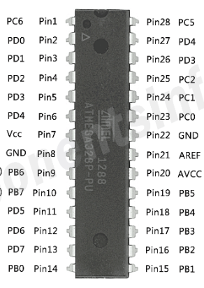
Pin Configuration
The Atmega3280 comes in a 40-pin DIP (Dual Inline Package) configuration. Below is the pinout description:
| Pin Number | Pin Name | Description |
|---|---|---|
| 1 | VCC | Power supply (1.8V - 5.5V) |
| 2 | GND | Ground |
| 3 | RESET | Active-low reset input |
| 4 | XTAL1 | External clock input |
| 5 | XTAL2 | External clock output |
| 6-13 | PORTB[0-7] | Digital I/O pins |
| 14-21 | PORTC[0-7] | Digital I/O pins or ADC inputs |
| 22-29 | PORTD[0-7] | Digital I/O pins |
| 30 | AVCC | Analog power supply for ADC |
| 31 | AREF | Reference voltage for ADC |
| 32 | ADC0 | Analog input channel 0 |
| 33-39 | ADC1-ADC7 | Analog input channels 1 to 7 |
| 40 | GND | Ground |
Usage Instructions
Using the Atmega3280 in a Circuit
- Power Supply: Connect the VCC pin to a regulated power source (1.8V to 5.5V) and the GND pin to ground.
- Clock Source: Use an external crystal oscillator (e.g., 16 MHz) connected to XTAL1 and XTAL2 for stable operation.
- Reset: Connect a pull-up resistor (e.g., 10 kΩ) to the RESET pin to ensure proper startup.
- I/O Pins: Configure the PORTB, PORTC, and PORTD pins as digital inputs or outputs in your code.
- ADC: Use the ADC pins (ADC0-ADC7) for analog-to-digital conversion. Connect the AREF pin to the desired reference voltage for ADC operations.
Best Practices
- Decouple the power supply with capacitors (e.g., 0.1 µF) near the VCC and AVCC pins to reduce noise.
- Use pull-up or pull-down resistors on unused pins to prevent floating inputs.
- Avoid exceeding the maximum voltage ratings to prevent damage to the microcontroller.
- Use low-power modes (e.g., sleep mode) to conserve energy in battery-powered applications.
Example: Interfacing with Arduino UNO
The Atmega3280 can be programmed using the Arduino IDE. Below is an example of reading an analog sensor and controlling an LED:
// Define pin connections
const int sensorPin = A0; // Analog sensor connected to ADC0
const int ledPin = 13;    // LED connected to digital pin 13

void setup() {
  pinMode(ledPin, OUTPUT); // Set LED pin as output
  Serial.begin(9600);      // Initialize serial communication
}

void loop() {
  int sensorValue = analogRead(sensorPin); // Read analog value from sensor
  Serial.println(sensorValue);            // Print sensor value to serial monitor

  // If sensor value exceeds threshold, turn on LED
  if (sensorValue > 512) {
    digitalWrite(ledPin, HIGH); // Turn on LED
  } else {
    digitalWrite(ledPin, LOW);  // Turn off LED
  }

  delay(100); // Wait for 100 ms
}
Troubleshooting and FAQs
Common Issues and Solutions
Microcontroller Not Responding
- Cause: Incorrect power supply or loose connections.
- Solution: Verify that the VCC and GND pins are properly connected and the voltage is within the specified range.
ADC Not Working
- Cause: Incorrect reference voltage or unconnected AREF pin.
- Solution: Ensure the AREF pin is connected to the desired reference voltage and the ADC is configured correctly in the code.
Program Upload Fails
- Cause: Incorrect bootloader or communication settings.
- Solution: Verify the correct bootloader is installed and the correct COM port and board are selected in the Arduino IDE.
High Power Consumption
- Cause: Unused peripherals or pins left floating.
- Solution: Disable unused peripherals in software and use pull-up or pull-down resistors on unused pins.
FAQs
Q: Can the Atmega3280 operate without an external crystal oscillator?
A: Yes, the Atmega3280 has an internal 8 MHz RC oscillator, but using an external crystal provides better accuracy.
Q: How do I protect the microcontroller from voltage spikes?
A: Use a voltage regulator and decoupling capacitors to stabilize the power supply and protect against spikes.
Q: Can I use the Atmega3280 for battery-powered applications?
A: Yes, the Atmega3280 supports low-power modes, making it suitable for battery-powered devices.
Q: What is the maximum current the I/O pins can source or sink?
A: Each I/O pin can source or sink up to 20 mA, with a total maximum current of 200 mA for all pins combined.