How to Use KQ330: Examples, Pinouts, and Specs
Introduction
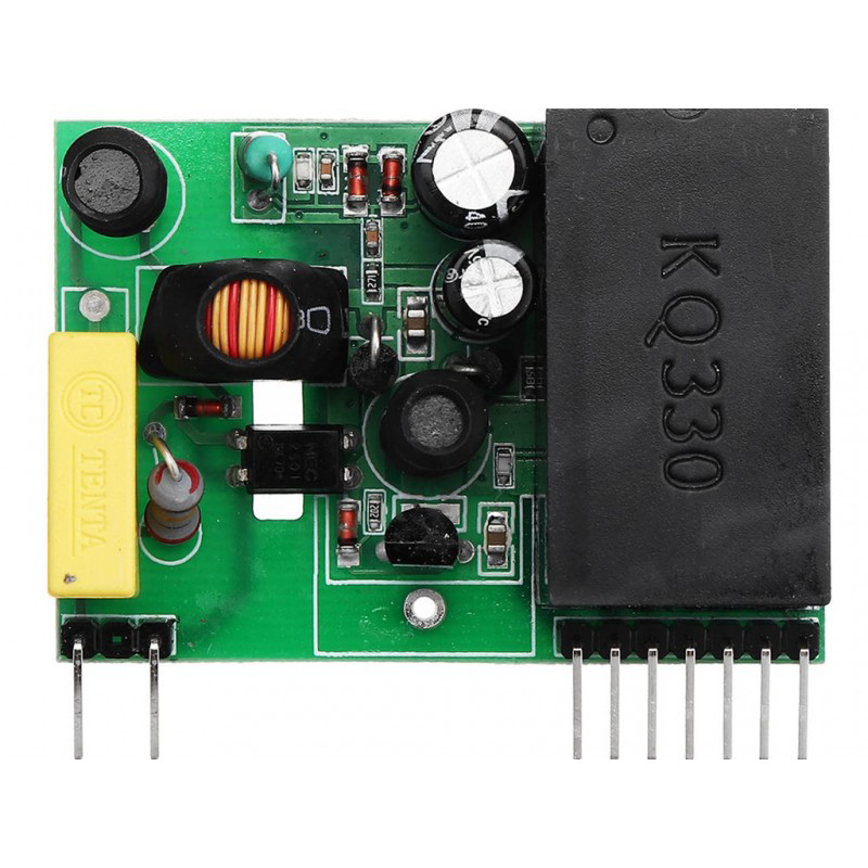
The KQ330 TTL UART Wireless Module, manufactured by Jin Wan Jie (or Generic), is a high-performance, low-power microcontroller designed for embedded applications. It features multiple I/O ports, integrated peripherals, and efficient processing capabilities, making it ideal for a wide range of wireless communication projects. The module supports TTL UART communication, enabling seamless integration with microcontrollers, such as Arduino, Raspberry Pi, and other embedded systems.
Explore Projects Built with KQ330
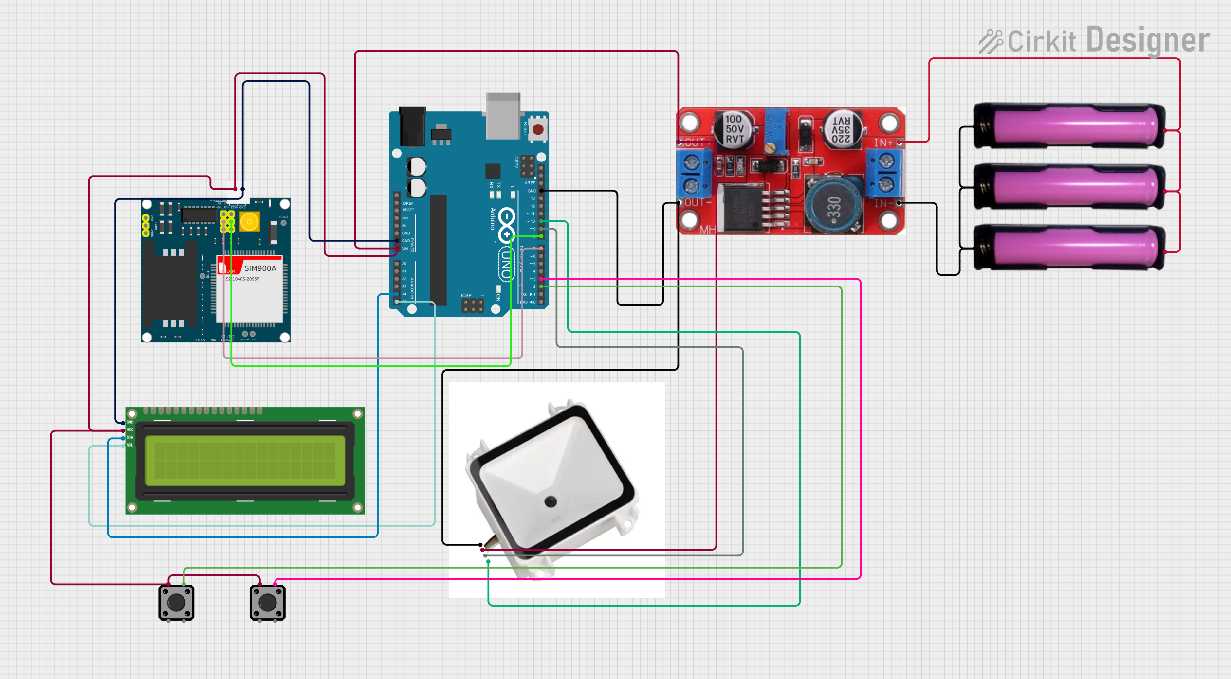


Explore Projects Built with KQ330
Common Applications and Use Cases
- Wireless data transmission in IoT devices
- Remote control systems
- Home automation and smart appliances
- Industrial monitoring and control
- Wireless sensor networks
- Robotics and drone communication
Technical Specifications
The KQ330 module is designed to deliver reliable performance while maintaining low power consumption. Below are its key technical details:
Key Technical Details
| Parameter | Specification |
|---|---|
| Operating Voltage | 3.3V to 5.0V |
| Communication Interface | TTL UART |
| Baud Rate | 9600 bps (default), configurable |
| Frequency Band | 433 MHz |
| Transmission Distance | Up to 100 meters (line of sight) |
| Power Consumption | < 50 mA |
| Operating Temperature | -40°C to +85°C |
| Dimensions | 25mm x 15mm x 3mm |
Pin Configuration and Descriptions
The KQ330 module has a simple 4-pin interface for easy integration into circuits. Below is the pinout:
| Pin Number | Pin Name | Description |
|---|---|---|
| 1 | VCC | Power supply input (3.3V to 5.0V) |
| 2 | GND | Ground connection |
| 3 | TXD | Transmit data (TTL UART output) |
| 4 | RXD | Receive data (TTL UART input) |
Usage Instructions
The KQ330 module is straightforward to use in wireless communication projects. Follow the steps below to integrate it into your circuit:
Step 1: Wiring the Module
- Connect the VCC pin of the KQ330 to a 3.3V or 5.0V power source.
- Connect the GND pin to the ground of your circuit.
- Connect the TXD pin of the KQ330 to the RX pin of your microcontroller (e.g., Arduino UNO).
- Connect the RXD pin of the KQ330 to the TX pin of your microcontroller.
Step 2: Configuring the Module
- The default baud rate of the KQ330 is 9600 bps. Ensure your microcontroller's UART settings match this baud rate.
- If needed, you can configure the baud rate and other parameters using AT commands (refer to the manufacturer's datasheet for details).
Step 3: Example Code for Arduino UNO
Below is an example Arduino sketch to send and receive data using the KQ330 module:
// Example code for KQ330 TTL UART Wireless Module with Arduino UNO
// This code sends a message and listens for incoming data

#include <SoftwareSerial.h>

// Define RX and TX pins for SoftwareSerial
SoftwareSerial KQ330(10, 11); // RX = Pin 10, TX = Pin 11

void setup() {
  Serial.begin(9600);         // Initialize Serial Monitor at 9600 bps
  KQ330.begin(9600);          // Initialize KQ330 at 9600 bps

  Serial.println("KQ330 Module Initialized");
  delay(1000);                // Wait for module to stabilize
}

void loop() {
  // Send data to the KQ330 module
  KQ330.println("Hello, KQ330!");

  // Check if data is available from the KQ330 module
  if (KQ330.available()) {
    String receivedData = KQ330.readString(); // Read incoming data
    Serial.print("Received: ");
    Serial.println(receivedData);            // Print received data to Serial Monitor
  }

  delay(1000); // Wait 1 second before sending the next message
}
Important Considerations and Best Practices
- Ensure the power supply voltage is within the specified range (3.3V to 5.0V) to avoid damaging the module.
- Use proper decoupling capacitors near the power pins to reduce noise and ensure stable operation.
- For long-distance communication, ensure a clear line of sight between the transmitter and receiver.
- Avoid placing the module near high-frequency noise sources or metal enclosures that may interfere with the signal.
Troubleshooting and FAQs
Common Issues and Solutions
No data transmission or reception:
- Verify the wiring connections, especially the TXD and RXD pins.
- Ensure the baud rate of the microcontroller matches the KQ330's baud rate (default: 9600 bps).
- Check the power supply voltage and ensure it is within the specified range.
Short communication range:
- Ensure there are no physical obstructions or interference sources between the transmitter and receiver.
- Use an external antenna if supported by the module to improve signal strength.
Module not responding to AT commands:
- Ensure the module is in AT command mode (refer to the manufacturer's datasheet for instructions).
- Double-check the UART settings and ensure proper termination of commands with a carriage return (
\r) and line feed (\n).
FAQs
Q: Can the KQ330 module be used with 5V logic microcontrollers?
A: Yes, the KQ330 supports both 3.3V and 5.0V logic levels, making it compatible with most microcontrollers.
Q: How can I change the default baud rate?
A: The baud rate can be changed using AT commands. Refer to the manufacturer's datasheet for the specific command syntax.
Q: What is the maximum data transmission distance?
A: The KQ330 can transmit data up to 100 meters in a clear line of sight. Obstacles and interference may reduce this range.
Q: Can I use multiple KQ330 modules in the same project?
A: Yes, multiple modules can be used, but ensure they are configured to operate on different channels or frequencies to avoid interference.
By following this documentation, you can effectively integrate and utilize the KQ330 TTL UART Wireless Module in your projects.