How to Use Balance Charging Module: Examples, Pinouts, and Specs
Introduction
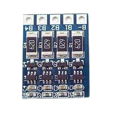
The Balance Charging Module is a critical component used in multi-cell battery packs to ensure that all cells are charged to the same voltage level. This process, known as "cell balancing," prevents overcharging of individual cells, which can lead to reduced battery life, overheating, or even safety hazards. By maintaining uniform voltage across all cells, the module enhances the overall performance, safety, and longevity of the battery pack.
Explore Projects Built with Balance Charging Module


Explore Projects Built with Balance Charging Module
Common Applications and Use Cases
- Lithium-ion (Li-ion) and Lithium Polymer (LiPo) battery packs
- Electric vehicles (EVs) and hybrid vehicles
- Uninterruptible Power Supplies (UPS)
- Solar energy storage systems
- Remote-controlled (RC) devices, drones, and robotics
- Portable electronics with multi-cell battery configurations
Technical Specifications
The Balance Charging Module is designed to work with a variety of battery chemistries and configurations. Below are the key technical details:
| Parameter | Value |
|---|---|
| Input Voltage Range | 4.2V to 24V (depending on the module type) |
| Supported Battery Types | Li-ion, LiPo, LiFePO4 |
| Balancing Current | Typically 30mA to 300mA |
| Number of Cells Supported | 2S to 6S (2 to 6 cells in series) |
| Operating Temperature | -20°C to 60°C |
| Efficiency | Up to 95% |
Pin Configuration and Descriptions
The module typically includes a connector for the battery pack and additional pins for power input and monitoring. Below is a general pinout description:
| Pin Name | Description |
|---|---|
| B+ | Positive terminal of the battery pack |
| B- | Negative terminal of the battery pack |
| BM1, BM2... | Intermediate connections for individual cell balancing |
| VCC | Power input for the module (if required) |
| GND | Ground connection |
Note: The exact pin configuration may vary depending on the specific module. Always refer to the datasheet of your module for precise details.
Usage Instructions
How to Use the Component in a Circuit
Connect the Battery Pack:
- Identify the positive (B+) and negative (B-) terminals of your battery pack.
- Connect the B+ and B- terminals of the module to the corresponding terminals of the battery pack.
- For multi-cell configurations, connect the intermediate cell terminals (BM1, BM2, etc.) to the module as per the cell arrangement.
Power the Module (if required):
- Some modules require an external power source. Connect the VCC and GND pins to a suitable power supply within the specified voltage range.
Monitor the Balancing Process:
- Many modules include LEDs or other indicators to show the status of the balancing process. Ensure all cells are balanced before disconnecting the module.
Important Considerations and Best Practices
- Verify Compatibility: Ensure the module supports the number of cells and battery chemistry of your pack.
- Avoid Overloading: Do not exceed the module's maximum balancing current or voltage rating.
- Secure Connections: Use proper connectors and ensure all connections are secure to avoid short circuits.
- Monitor Temperature: Avoid operating the module in environments exceeding its temperature range.
- Use with a Charger: The module is typically used in conjunction with a compatible battery charger.
Example: Using with an Arduino UNO
While the Balance Charging Module is not directly programmable, you can use an Arduino UNO to monitor the voltage of individual cells during the balancing process. Below is an example code snippet:
// Example: Monitoring cell voltages with Arduino UNO
// Connect the cell voltage outputs (BM1, BM2, etc.) to analog pins on the Arduino

const int cell1Pin = A0; // BM1 connected to analog pin A0
const int cell2Pin = A1; // BM2 connected to analog pin A1
const int cell3Pin = A2; // BM3 connected to analog pin A2

void setup() {
  Serial.begin(9600); // Initialize serial communication
}

void loop() {
  // Read cell voltages
  float cell1Voltage = analogRead(cell1Pin) * (5.0 / 1023.0) * 4.2; // Adjust scaling
  float cell2Voltage = analogRead(cell2Pin) * (5.0 / 1023.0) * 4.2;
  float cell3Voltage = analogRead(cell3Pin) * (5.0 / 1023.0) * 4.2;

  // Print cell voltages to the Serial Monitor
  Serial.print("Cell 1 Voltage: ");
  Serial.print(cell1Voltage);
  Serial.println(" V");

  Serial.print("Cell 2 Voltage: ");
  Serial.print(cell2Voltage);
  Serial.println(" V");

  Serial.print("Cell 3 Voltage: ");
  Serial.print(cell3Voltage);
  Serial.println(" V");

  delay(1000); // Wait for 1 second before the next reading
}
Note: Adjust the scaling factor in the code based on your specific module and voltage divider circuit.
Troubleshooting and FAQs
Common Issues and Solutions
Module Not Balancing Cells:
- Cause: Incorrect wiring or incompatible battery pack.
- Solution: Double-check all connections and ensure the module supports your battery configuration.
Overheating:
- Cause: Excessive balancing current or poor ventilation.
- Solution: Reduce the load or improve airflow around the module.
LED Indicators Not Working:
- Cause: Faulty module or insufficient power supply.
- Solution: Verify the power supply voltage and check for any damaged components.
Uneven Cell Voltages After Balancing:
- Cause: Faulty cell or insufficient balancing current.
- Solution: Test individual cells for defects and consider using a higher-capacity module.
FAQs
Q: Can I use the module with a single-cell battery?
A: No, the Balance Charging Module is designed for multi-cell battery packs. For single-cell batteries, use a standard charger.
Q: How long does the balancing process take?
A: The time depends on the initial voltage difference between cells and the module's balancing current. It can range from minutes to several hours.
Q: Is the module safe to use with high-capacity batteries?
A: Yes, as long as the module's specifications match the battery pack's voltage and current requirements.
Q: Can I use the module without a charger?
A: No, the module is designed to work alongside a charger to ensure proper cell balancing during the charging process.