Cirkit Designer Logo
Cirkit Designer
Your all-in-one circuit design IDE
Home / 
Component Documentation

How to Use red light 220vac: Examples, Pinouts, and Specs

Image of red light 220vac
Cirkit Designer LogoDesign with red light 220vac in Cirkit Designer

Introduction

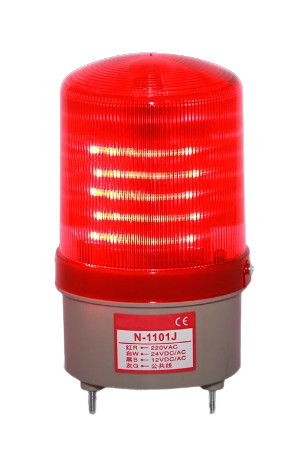
The Red Light Emitting Component designed for 220V AC is a visual indicator device commonly used in various applications such as power status indicators, warning signals, and decorative lighting. This component is specifically engineered to operate directly with 220V AC mains power, making it suitable for household and industrial environments.

Explore Projects Built with red light 220vac

Use Cirkit Designer to design, explore, and prototype these projects online. Some projects support real-time simulation. Click "Open Project" to start designing instantly!
LED Indicator Circuit with Push Switches and Voltage Regulation
Image of circuit 1: A project utilizing red light 220vac in a practical application
This circuit converts 220V AC to 24V DC using a power transformer and a bridge rectifier, then regulates the voltage to a stable output using a voltage regulator. It includes multiple LEDs controlled by push switches, with current limiting provided by a resistor.
Cirkit Designer LogoOpen Project in Cirkit Designer
220V AC Bulb Control Circuit with Rocker Switch
Image of Copy of Lampu Kuning: A project utilizing red light 220vac in a practical application
This circuit is a simple AC power control circuit designed to power an AC bulb using a 220V power source. It includes a rocker switch that acts as an on/off control for the bulb. When the switch is closed, it completes the circuit allowing current to flow through the bulb, thus turning it on.
Cirkit Designer LogoOpen Project in Cirkit Designer
Arduino UNO Controlled Relay Switch for 220V AC Light
Image of push button-lamp: A project utilizing red light 220vac in a practical application
This circuit uses an Arduino UNO to control a 5V relay with a pushbutton. When the button is pressed, the Arduino toggles the relay state, which in turn controls the power to a 220VAC red light. The power supply provides 5V to the Arduino and relay, and also connects to the relay's common terminal to switch the 220VAC line for the red light.
Cirkit Designer LogoOpen Project in Cirkit Designer
Wi-Fi Enabled Motion-Activated Lighting System with Radar Sensor
Image of CAPSTONE: A project utilizing red light 220vac in a practical application
This circuit is designed to control an AC LED bulb using a 220V power source, with an infrared motion sensor and an MMWave radar sensor providing input signals. The two-channel relay is used to switch the LED bulb on and off based on the sensor inputs, while the ESP8266 microcontroller is likely programmed to process the sensor data and control the relay. A converter is included to interface between the sensors, microcontroller, and the relay, ensuring proper voltage levels.
Cirkit Designer LogoOpen Project in Cirkit Designer

Explore Projects Built with red light 220vac

Use Cirkit Designer to design, explore, and prototype these projects online. Some projects support real-time simulation. Click "Open Project" to start designing instantly!
Image of circuit 1: A project utilizing red light 220vac in a practical application
LED Indicator Circuit with Push Switches and Voltage Regulation
This circuit converts 220V AC to 24V DC using a power transformer and a bridge rectifier, then regulates the voltage to a stable output using a voltage regulator. It includes multiple LEDs controlled by push switches, with current limiting provided by a resistor.
Cirkit Designer LogoOpen Project in Cirkit Designer
Image of Copy of Lampu Kuning: A project utilizing red light 220vac in a practical application
220V AC Bulb Control Circuit with Rocker Switch
This circuit is a simple AC power control circuit designed to power an AC bulb using a 220V power source. It includes a rocker switch that acts as an on/off control for the bulb. When the switch is closed, it completes the circuit allowing current to flow through the bulb, thus turning it on.
Cirkit Designer LogoOpen Project in Cirkit Designer
Image of push button-lamp: A project utilizing red light 220vac in a practical application
Arduino UNO Controlled Relay Switch for 220V AC Light
This circuit uses an Arduino UNO to control a 5V relay with a pushbutton. When the button is pressed, the Arduino toggles the relay state, which in turn controls the power to a 220VAC red light. The power supply provides 5V to the Arduino and relay, and also connects to the relay's common terminal to switch the 220VAC line for the red light.
Cirkit Designer LogoOpen Project in Cirkit Designer
Image of CAPSTONE: A project utilizing red light 220vac in a practical application
Wi-Fi Enabled Motion-Activated Lighting System with Radar Sensor
This circuit is designed to control an AC LED bulb using a 220V power source, with an infrared motion sensor and an MMWave radar sensor providing input signals. The two-channel relay is used to switch the LED bulb on and off based on the sensor inputs, while the ESP8266 microcontroller is likely programmed to process the sensor data and control the relay. A converter is included to interface between the sensors, microcontroller, and the relay, ensuring proper voltage levels.
Cirkit Designer LogoOpen Project in Cirkit Designer

Common Applications and Use Cases

  • Power Status Indicators: To indicate the on/off status of machinery, appliances, or circuits.
  • Warning Signals: In safety-critical systems to alert users of potential dangers.
  • Decorative Lighting: For aesthetic purposes in commercial and residential spaces.
  • Control Panels: As a part of user interfaces in various electronic control systems.

Technical Specifications

Key Technical Details

Parameter Specification
Operating Voltage 220V AC
Light Color Red
Power Consumption Typically 10-20mA
Lifespan Approx. 25,000 hours
Operating Temperature -10°C to +50°C

Pin Configuration and Descriptions

As this is a 220V AC component, it does not have a traditional pin configuration like low-voltage DC components. Instead, it has two wire leads:

Lead Description Function
Live (L) Connects to the phase line of AC mains
Neutral (N) Connects to the neutral line of AC mains

Usage Instructions

How to Use the Component in a Circuit

  1. Power Source: Ensure the power source is 220V AC with proper grounding.
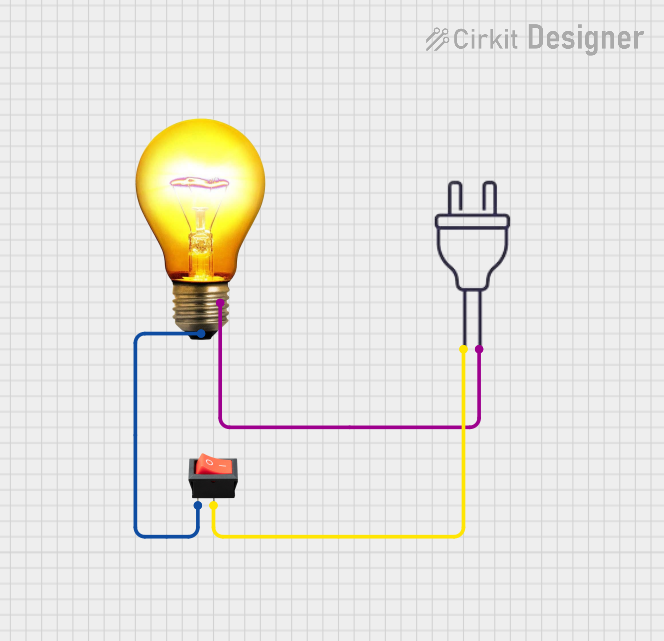
  2. Wiring: Connect the Live (L) lead to the phase line and the Neutral (N) lead to the neutral line of the AC mains.
  3. Switching: To control the light, incorporate a switch in the Live (L) lead.
  4. Safety: Always use an appropriate fuse and ensure that the wiring is capable of handling the current draw.

Important Considerations and Best Practices

  • Isolation: When integrating with low-voltage electronics, ensure proper isolation from the high-voltage AC circuit to prevent electrical hazards.
  • Heat Dissipation: Provide adequate ventilation around the component as it may generate heat during operation.
  • Mounting: Secure the component in a suitable fixture that can handle high voltage.
  • Regulations: Comply with local electrical codes and standards for AC wiring and installation.

Troubleshooting and FAQs

Common Issues

  • Light Not Emitting: Check the AC mains connection, ensure the switch is on, and verify that the component is not damaged.
  • Flickering Light: This may indicate a loose connection or fluctuation in the AC mains. Ensure all connections are secure.

Solutions and Tips for Troubleshooting

  • Secure Connections: Periodically check and tighten the wire connections to the component.
  • Replace if Damaged: If the light does not emit after checking connections, replace the component as it may be at the end of its lifespan.

FAQs

Q: Can I use this component with a dimmer switch? A: It depends on the design of the component. Some AC-powered lights can work with dimmers, but you should check the manufacturer's specifications.

Q: Is it safe to handle the component when powered? A: No, always turn off the power and ensure the circuit is not live before handling the component.

Q: Can I use this component outdoors? A: This depends on the component's rating. If it is not rated for outdoor use, it should be placed within a suitable weatherproof enclosure.

Q: How can I extend the lifespan of the component? A: Avoid frequent on/off cycles and ensure it operates within the specified temperature range.

Code Example for Arduino UNO (For Illustrative Purposes)

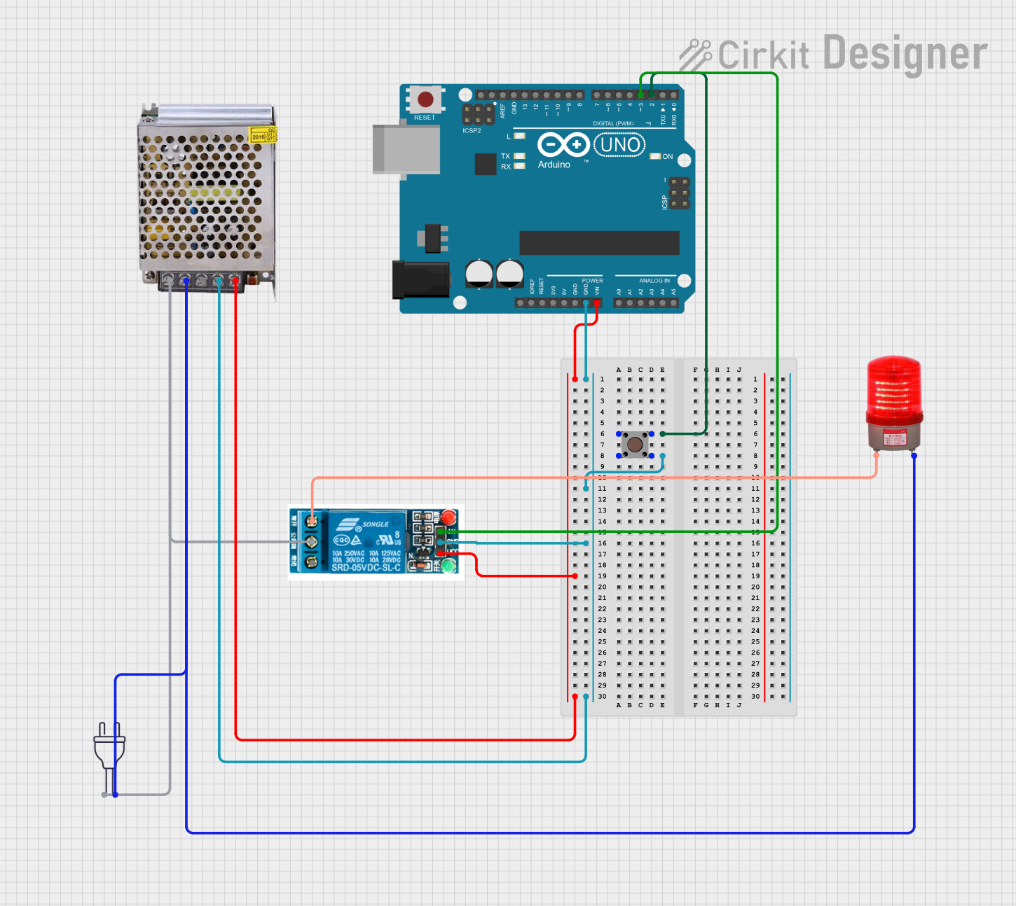
Since the component operates on 220V AC, it cannot be directly interfaced with an Arduino UNO. However, if you wish to control the light using an Arduino, you would need to use a relay module that can handle 220V AC loads. Below is an example code snippet for turning the red light on and off using an Arduino and a relay.

// Define the relay control pin
const int relayPin = 2;

void setup() {
  // Set the relay pin as an output
  pinMode(relayPin, OUTPUT);
}

void loop() {
  // Turn on the red light (relay closes the circuit)
  digitalWrite(relayPin, HIGH);
  delay(1000); // Keep the light on for 1 second
  
  // Turn off the red light (relay opens the circuit)
  digitalWrite(relayPin, LOW);
  delay(1000); // Keep the light off for 1 second
}

Note: The above code is for demonstration purposes only. When working with 220V AC, always ensure safety and compliance with electrical standards. Use a relay module that is rated for 220V AC and has appropriate isolation between the low-voltage control side and the high-voltage load side.