How to Use arducam : Examples, Pinouts, and Specs
Introduction
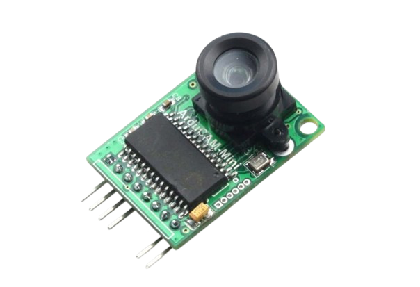
The Arducam OV2640 camera module is a versatile and compact imaging solution that provides a 2-megapixel resolution and is capable of capturing both still images and video. It is designed to be interfaced with microcontrollers and development boards like the Arduino UNO, making it an ideal component for a wide range of applications such as surveillance, robotics, environmental monitoring, and DIY projects that require visual capabilities.
Explore Projects Built with arducam
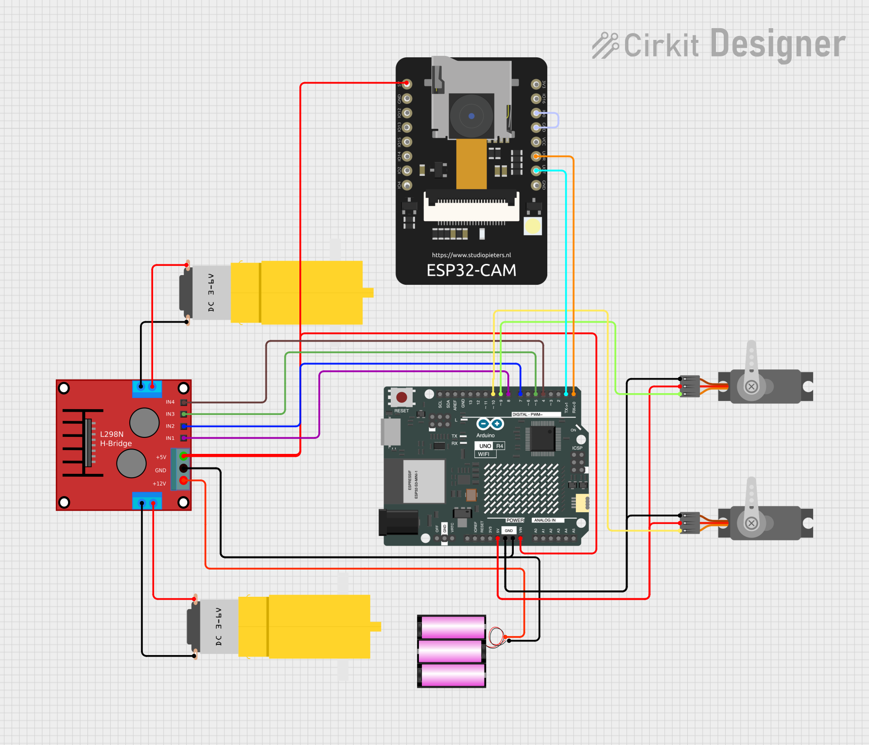
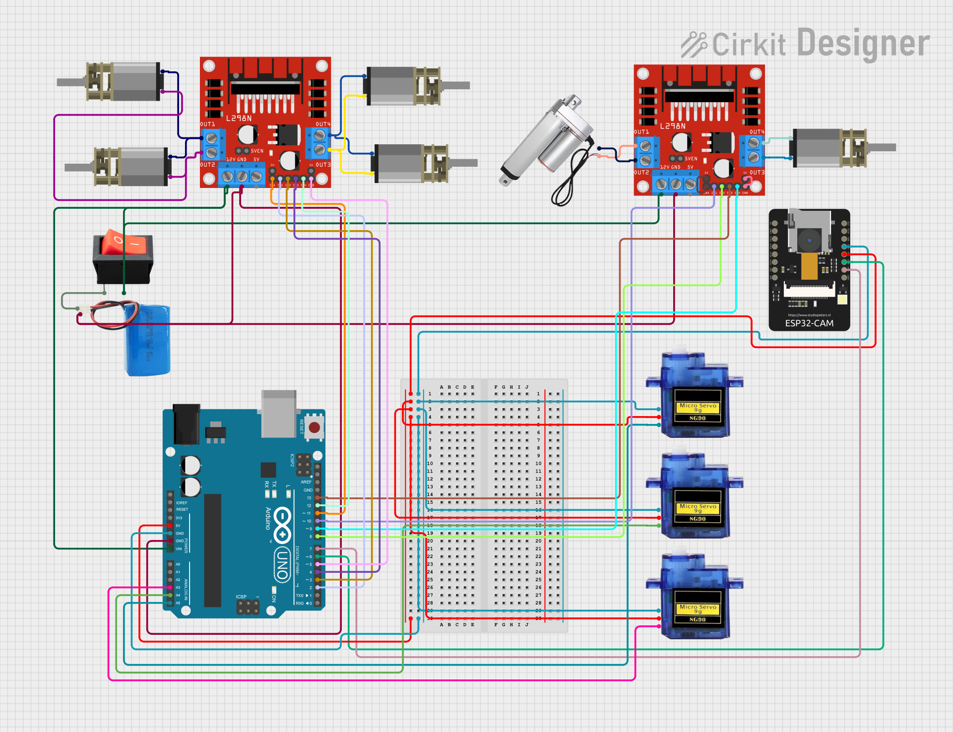
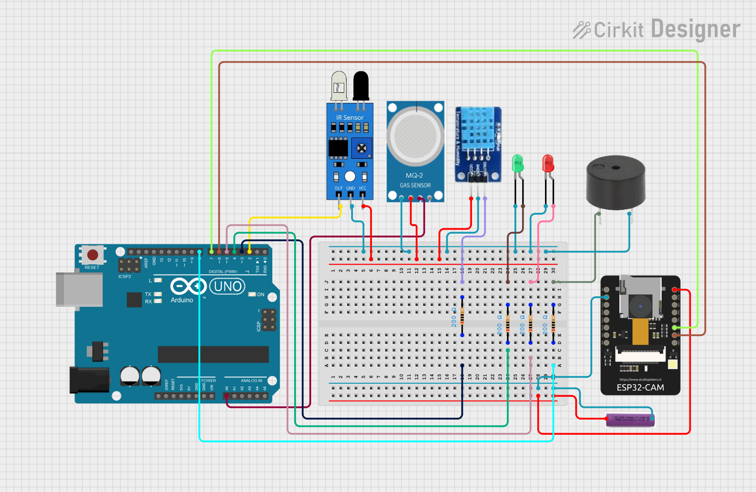
Explore Projects Built with arducam
Common Applications and Use Cases
- Robotics: Vision for navigation and object recognition.
- Surveillance: Security cameras and motion detection systems.
- Environmental Monitoring: Capturing images for analysis.
- DIY Projects: Custom-built cameras or interactive art installations.
Technical Specifications
Key Technical Details
- Resolution: 2 Megapixels
- Array Size: UXGA 1622x1200
- Power Supply: Core: 1.5VDC + 5%, Analog: 2.6 to 3.0V, I/O: 1.7 to 3.0V
- Operating Temperature: -30°C to 70°C
- Output Formats: (8-bit): YUV(422/420)/YCbCr422, RGB565/555, 8-bit compressed data
- Lens: 1/4 inch
- Field of View: 60 degrees
- Maximum Image Transfer Rate: UXGA 15fps, SVGA 30fps, CIF 60fps
- Sensitivity: 1.3V / (Lux-sec)
- Signal to Noise Ratio: 40 dB
- Dynamic Range: 50 dB
- Interface: Serial Camera Control Bus (SCCB)
Pin Configuration and Descriptions
| Pin No. | Name | Description |
|---|---|---|
| 1 | VCC | Power supply (3.3V) |
| 2 | GND | Ground connection |
| 3 | SIOC | SCCB Control Clock |
| 4 | SIOD | SCCB Control Data |
| 5 | VSYNC | Vertical synchronization |
| 6 | HREF | Horizontal reference signal |
| 7 | PCLK | Pixel Clock |
| 8 | XCLK | System Clock |
| 9-16 | D0-D7 | Data Ports |
Usage Instructions
How to Use the Component in a Circuit
- Power Supply: Connect the VCC pin to a 3.3V source and the GND pin to the ground.
- Data Interface: Connect the data pins (D0-D7) to the microcontroller's data input pins.
- Clocks: Connect the XCLK pin to an external clock source if required.
- Control Interface: Connect the SIOC and SIOD pins to the microcontroller for SCCB communication.
- Synchronization: Connect the VSYNC and HREF pins to the microcontroller to handle frame synchronization.
Important Considerations and Best Practices
- Ensure that the power supply is stable and within the specified voltage range to prevent damage.
- Use appropriate level shifters if interfacing with a 5V microcontroller to match the 3.3V logic level of the camera module.
- Keep the connection wires as short as possible to minimize signal degradation, especially for the clock and data signals.
- It is recommended to use a dedicated library or driver for interfacing with the OV2640 to simplify the development process.
Troubleshooting and FAQs
Common Issues Users Might Face
- No Image Data: Ensure that all connections are secure and the power supply is within the specified range.
- Corrupted Images: Check for proper grounding and stable power supply. Also, verify that the clock signals are clean and stable.
- SCCB Communication Failure: Confirm that the SIOC and SIOD lines are correctly connected and that the microcontroller is correctly configured for SCCB communication.
Solutions and Tips for Troubleshooting
- Double-check wiring against the pin configuration table.
- Use oscilloscope to verify signal integrity on data and clock lines.
- Consult the Arducam community forums or technical support for assistance.
FAQs
Q: Can I use the Arducam OV2640 with an Arduino UNO? A: Yes, the OV2640 can be used with an Arduino UNO, but you will need a level shifter for the 3.3V logic level and a library that supports the camera module.
Q: What is the maximum frame rate I can achieve with the OV2640? A: The maximum frame rate depends on the resolution. At full resolution (UXGA), you can achieve up to 15fps.
Q: How do I focus the camera module? A: The lens of the OV2640 can be manually adjusted by rotating it to achieve the desired focus.
Q: Is there a library available for interfacing the OV2640 with an Arduino? A: Yes, there are libraries available such as the Arducam Mini module library that can be used with Arduino.
Example Code for Arduino UNO
Below is an example code snippet for initializing the OV2640 camera module with an Arduino UNO. This code assumes the use of the Arducam Mini library.
#include <ArduCAM.h>
#include <SPI.h>
#include <Wire.h>
#include "memorysaver.h"

// This demo can only work on ArduCAM Mini board with OV2640 sensor.
#if !(defined OV2640_MINI_2MP)
#error Please select the hardware platform and camera module in the ../libraries/ArduCAM/memorysaver.h file
#endif

// Set pin definitions
#define CS_PIN 7 // Chip select pin

ArduCAM myCAM(OV2640, CS_PIN);

void setup() {
  // Initialize serial communication
  Serial.begin(115200);
  // Initialize SPI
  SPI.begin();
  // Initialize camera
  myCAM.write_reg(ARDUCHIP_TEST1, 0x55);
  uint8_t temp = myCAM.read_reg(ARDUCHIP_TEST1);
  if (temp != 0x55) {
    Serial.println(F("SPI interface Error!"));
    while (1);
  }
  // Camera initialization
  myCAM.set_format(JPEG);
  myCAM.InitCAM();
  myCAM.OV2640_set_JPEG_size(OV2640_320x240);
}

void loop() {
  // Capture and process image data
  // ...
}
Please note that this code is for illustration purposes only and may require additional setup and handling for capturing and processing image data. Always refer to the latest library documentation and examples for the most accurate and up-to-date usage information.