How to Use 12v RELAY: Examples, Pinouts, and Specs
Introduction
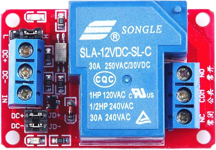
A 12V relay is an electromechanical switch that allows a low-power circuit to switch a relatively high current or voltage on and off. It consists of a coil, an armature, a spring, and a set of electrical contacts. When the coil is energized with 12V, it creates a magnetic field that pulls the armature and changes the position of the contacts. Relays are commonly used in applications where it is necessary to control a circuit by a separate low-power signal, such as in automotive electronics, home automation, and industrial controls.
Explore Projects Built with 12v RELAY


Explore Projects Built with 12v RELAY
Technical Specifications
Key Technical Details
- Operating Voltage: 12V DC
- Coil Resistance: Typically 400Ω
- Contact Capacity: Normally Open (NO) / Normally Closed (NC) contacts
- Max Switching Voltage: Up to 250V AC or 30V DC
- Max Switching Current: Up to 10A (AC) or 10A (DC)
- Operate Time: Typically 10ms
- Release Time: Typically 5ms
- Life Expectancy: Mechanical (up to 10 million operations), Electrical (up to 100,000 operations)
Pin Configuration and Descriptions
| Pin Number | Description | Type |
|---|---|---|
| 1 | Coil End 1 | Input |
| 2 | Coil End 2 | Input |
| 3 | Common (COM) | Output |
| 4 | Normally Closed (NC) | Output |
| 5 | Normally Open (NO) | Output |
Usage Instructions
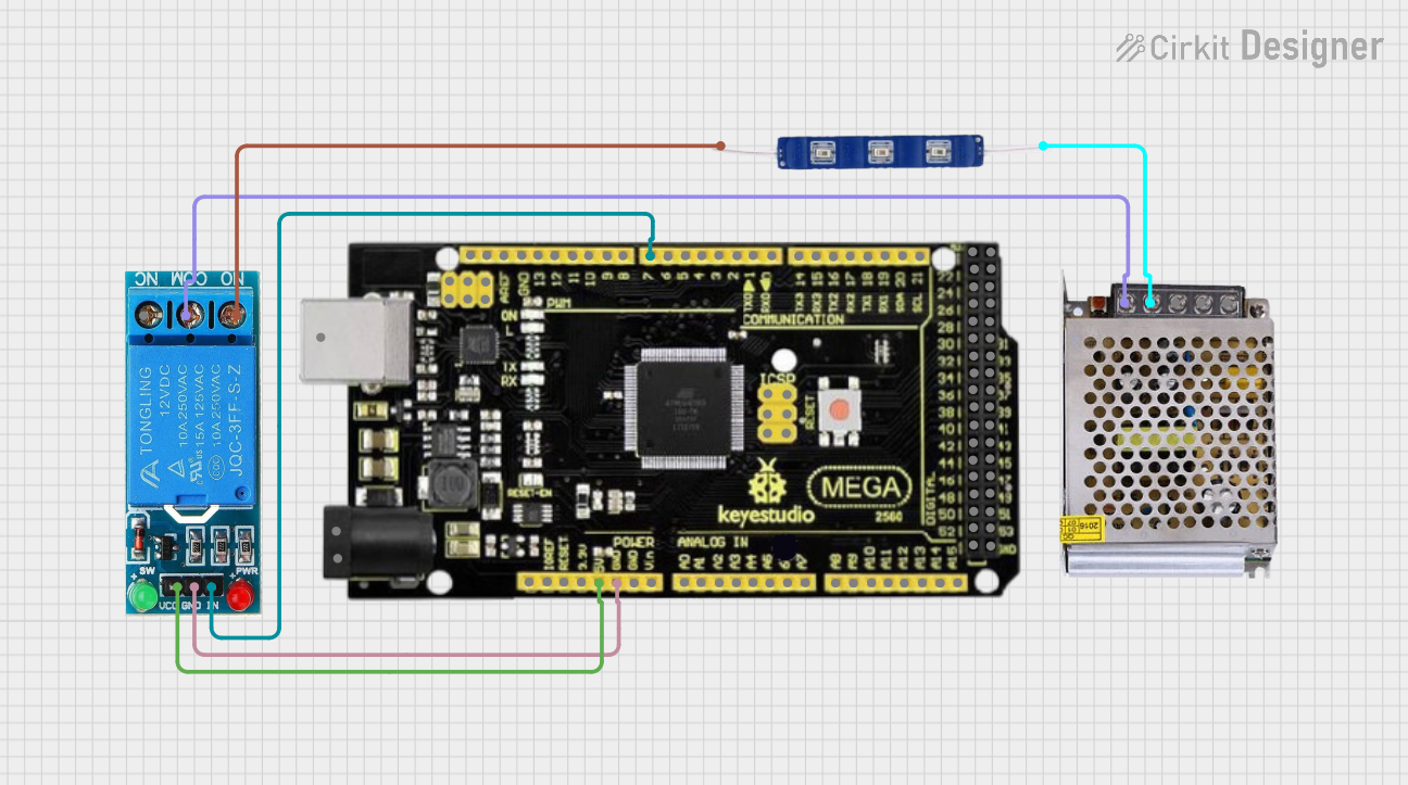
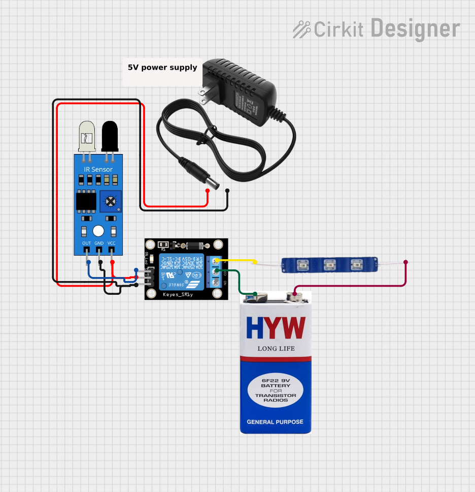
How to Use the Component in a Circuit
Powering the Coil:
- Connect the 12V power supply to the coil pins (1 and 2). Ensure correct polarity if the relay has a diode for coil protection.
Connecting the Load:
- Connect the device you want to control to the Common (COM) pin (3).
- For a normally open operation, connect the other end of the device to the Normally Open (NO) pin (5).
- For a normally closed operation, connect the other end of the device to the Normally Closed (NC) pin (4).
Driving the Relay:
- Use a transistor or a relay driver IC if the control signal is not sufficient to drive the relay coil directly.
- Include a flyback diode across the coil to prevent back EMF damage to the control circuitry.
Important Considerations and Best Practices
- Voltage Rating: Do not exceed the rated control voltage of the relay coil.
- Current Rating: Ensure the load does not exceed the relay's maximum current rating.
- Inductive Loads: When switching inductive loads, use a snubber circuit to manage voltage spikes.
- Mounting: Use a relay socket or PCB mount for secure and easy installation.
- Safety: Always disconnect power before working on the relay circuit.
Troubleshooting and FAQs
Common Issues
Relay Does Not Actuate:
- Check if the coil is receiving the correct voltage.
- Verify that the control circuit is providing enough current to energize the coil.
- Inspect for any physical damage to the relay.
Intermittent Operation:
- Ensure that all connections are secure.
- Check for any signs of overheating or contact wear.
Contacts Not Switching:
- Verify that the contacts are not welded shut due to overcurrent.
- Inspect the relay for any foreign particles or dust.
Solutions and Tips
Use a Multimeter:
- Test the coil resistance to ensure it is within specifications.
- Check for continuity across the contacts in their respective states (NO or NC).
Preventive Maintenance:
- Regularly inspect the relay for any signs of wear or damage.
- Replace the relay if it has reached the end of its electrical life expectancy.
FAQs
Q: Can I use a 12V relay with a 5V signal? A: Yes, but you will need a transistor or relay driver circuit to step up the voltage to 12V for the coil.
Q: How do I know if my relay is working? A: You can listen for a clicking sound when the relay is activated, or use a multimeter to check for continuity across the contacts.
Q: Can I switch AC loads with a 12V DC relay? A: Yes, as long as the load does not exceed the relay's maximum voltage and current ratings for AC.
Q: Why is my relay getting hot? A: It may be due to overloading, continuous operation, or insufficient de-rating. Ensure the load is within the relay's specifications.
Example Code for Arduino UNO
// Example code to control a 12V relay with an Arduino UNO
const int relayPin = 2; // Relay connected to digital pin 2

void setup() {
  pinMode(relayPin, OUTPUT); // Set relay pin as an output
}

void loop() {
  digitalWrite(relayPin, HIGH); // Turn on the relay
  delay(1000);                  // Wait for 1 second
  digitalWrite(relayPin, LOW);  // Turn off the relay
  delay(1000);                  // Wait for 1 second
}
Note: When connecting a 12V relay to an Arduino, ensure you use a suitable driver circuit to protect the microcontroller from high voltage and current.