Cirkit Designer Logo
Cirkit Designer
Your all-in-one circuit design IDE
Home / 
Component Documentation

How to Use NAU7802 ADC Converter: Examples, Pinouts, and Specs

Image of NAU7802 ADC Converter
Cirkit Designer LogoDesign with NAU7802 ADC Converter in Cirkit Designer

Introduction

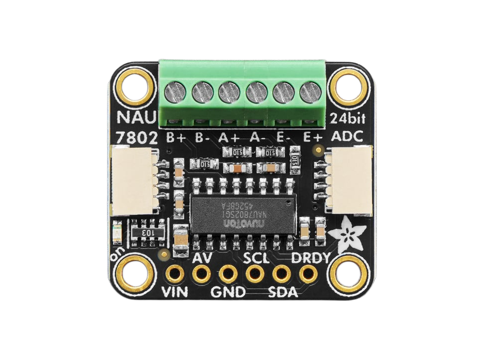
The NAU7802 24-Bit ADC by Adafruit is a high-precision, low-power analog-to-digital converter (ADC) designed for applications requiring accurate measurement of analog signals. It is particularly well-suited for weighing scales, load cells, and other precision measurement systems. The NAU7802 features a 24-bit resolution, an integrated programmable gain amplifier (PGA), and supports I2C communication, making it easy to interface with microcontrollers such as the Arduino UNO or Raspberry Pi.

Explore Projects Built with NAU7802 ADC Converter

Use Cirkit Designer to design, explore, and prototype these projects online. Some projects support real-time simulation. Click "Open Project" to start designing instantly!
ESP32-Controlled Smart Lighting System with Power Monitoring
Image of Energy Monitoring System: A project utilizing NAU7802 ADC Converter in a practical application
This circuit appears to be a multi-channel current monitoring system using several ACS712 current sensors to measure the current through different loads, likely bulbs connected to a 220V power source. The current readings from the sensors are digitized by an Adafruit ADS1115 16-bit ADC, which interfaces with an ESP32 microcontroller via I2C communication for further processing or telemetry. A buck converter is used to step down the voltage to power the ESP32 and the sensors, and the system is powered through a 2.1mm DC barrel jack, indicating it is designed for external power supply.
Cirkit Designer LogoOpen Project in Cirkit Designer
Arduino UNO WiFi Sensor Data Acquisition and Display System
Image of Senior Design: A project utilizing NAU7802 ADC Converter in a practical application
This circuit features an Arduino UNO R4 WiFi microcontroller interfacing with a 4-channel ADC to read from various sensors and display data on an I2C LCD screen. A pushbutton provides user input, and a DC-DC buck converter regulates the power supply from a 12V source.
Cirkit Designer LogoOpen Project in Cirkit Designer
Arduino UNO with ADS1115 ADC and ACS712 Current Sensor Monitoring System
Image of ADC: A project utilizing NAU7802 ADC Converter in a practical application
This circuit features an Arduino UNO microcontroller interfaced with an ADS1115 ADC for precise analog-to-digital conversion, an ACS712 current sensor for current measurement, and a potentiometer for adjustable input. It includes toggle switches and a push button for user input, with the Arduino programmed to read and process sensor data, switch states, and potentiometer values, outputting the information via serial communication for monitoring or further processing.
Cirkit Designer LogoOpen Project in Cirkit Designer
ESP32-Based Multi-Sensor Monitoring System with Battery Power
Image of Wind turbine 2.0: A project utilizing NAU7802 ADC Converter in a practical application
This circuit is a sensor monitoring system powered by a 7.4V battery, regulated to 5V using a 7805 voltage regulator. It uses an ESP32 microcontroller to interface with an ADXL345 accelerometer, INA219 current sensor, BMP280 pressure sensor, and an IR sensor, all connected via I2C and GPIO for data acquisition and processing.
Cirkit Designer LogoOpen Project in Cirkit Designer

Explore Projects Built with NAU7802 ADC Converter

Use Cirkit Designer to design, explore, and prototype these projects online. Some projects support real-time simulation. Click "Open Project" to start designing instantly!
Image of Energy Monitoring System: A project utilizing NAU7802 ADC Converter in a practical application
ESP32-Controlled Smart Lighting System with Power Monitoring
This circuit appears to be a multi-channel current monitoring system using several ACS712 current sensors to measure the current through different loads, likely bulbs connected to a 220V power source. The current readings from the sensors are digitized by an Adafruit ADS1115 16-bit ADC, which interfaces with an ESP32 microcontroller via I2C communication for further processing or telemetry. A buck converter is used to step down the voltage to power the ESP32 and the sensors, and the system is powered through a 2.1mm DC barrel jack, indicating it is designed for external power supply.
Cirkit Designer LogoOpen Project in Cirkit Designer
Image of Senior Design: A project utilizing NAU7802 ADC Converter in a practical application
Arduino UNO WiFi Sensor Data Acquisition and Display System
This circuit features an Arduino UNO R4 WiFi microcontroller interfacing with a 4-channel ADC to read from various sensors and display data on an I2C LCD screen. A pushbutton provides user input, and a DC-DC buck converter regulates the power supply from a 12V source.
Cirkit Designer LogoOpen Project in Cirkit Designer
Image of ADC: A project utilizing NAU7802 ADC Converter in a practical application
Arduino UNO with ADS1115 ADC and ACS712 Current Sensor Monitoring System
This circuit features an Arduino UNO microcontroller interfaced with an ADS1115 ADC for precise analog-to-digital conversion, an ACS712 current sensor for current measurement, and a potentiometer for adjustable input. It includes toggle switches and a push button for user input, with the Arduino programmed to read and process sensor data, switch states, and potentiometer values, outputting the information via serial communication for monitoring or further processing.
Cirkit Designer LogoOpen Project in Cirkit Designer
Image of Wind turbine 2.0: A project utilizing NAU7802 ADC Converter in a practical application
ESP32-Based Multi-Sensor Monitoring System with Battery Power
This circuit is a sensor monitoring system powered by a 7.4V battery, regulated to 5V using a 7805 voltage regulator. It uses an ESP32 microcontroller to interface with an ADXL345 accelerometer, INA219 current sensor, BMP280 pressure sensor, and an IR sensor, all connected via I2C and GPIO for data acquisition and processing.
Cirkit Designer LogoOpen Project in Cirkit Designer

Common Applications

  • Weighing scales and load cell systems
  • Industrial measurement systems
  • Portable instrumentation
  • IoT devices requiring precise analog signal measurement
  • Sensor data acquisition

Technical Specifications

The following table outlines the key technical details of the NAU7802 ADC:

Parameter Value
Resolution 24-bit
Input Voltage Range 0V to AVDD (Analog Supply Voltage)
Analog Supply Voltage (AVDD) 2.7V to 5.5V
Digital Supply Voltage (DVDD) 1.8V to 3.6V
Programmable Gain 1x, 2x, 4x, 8x, 16x, 32x, 64x
Communication Interface I2C
I2C Address (Default) 0x2A
Operating Temperature Range -40°C to +85°C
Power Consumption Low-power mode: ~1.2mA

Pin Configuration

The NAU7802 ADC is available on a breakout board with the following pin configuration:

Pin Name Description
VIN Power input (3.3V or 5V)
GND Ground
SCL I2C clock line
SDA I2C data line
DRDY Data ready output (optional, for interrupt use)
F1, F2 Filter pins (not typically used in basic setups)

Usage Instructions

Connecting the NAU7802 to an Arduino UNO

To use the NAU7802 ADC with an Arduino UNO, follow these steps:

  1. Wiring:

    • Connect the VIN pin of the NAU7802 to the 5V pin on the Arduino.
    • Connect the GND pin of the NAU7802 to the GND pin on the Arduino.
    • Connect the SCL pin of the NAU7802 to the A5 pin on the Arduino (I2C clock line).
    • Connect the SDA pin of the NAU7802 to the A4 pin on the Arduino (I2C data line).
  2. Install Required Libraries:

    • Install the Adafruit NAU7802 library from the Arduino Library Manager.
  3. Example Code: Use the following example code to read data from the NAU7802:

    #include <Wire.h>
    #include <Adafruit_NAU7802.h>
    
    // Create an instance of the NAU7802 ADC
    Adafruit_NAU7802 nau7802;
    
    void setup() {
      Serial.begin(115200); // Initialize serial communication
      while (!Serial);      // Wait for the serial monitor to open
    
      // Initialize the NAU7802
      if (!nau7802.begin()) {
        Serial.println("Failed to find NAU7802 chip!");
        while (1); // Halt execution if the chip is not found
      }
      Serial.println("NAU7802 found!");
    
      // Calibrate the internal offset
      if (!nau7802.calibrateAFE()) {
        Serial.println("Failed to calibrate AFE!");
        while (1); // Halt execution if calibration fails
      }
      Serial.println("Calibration complete.");
    }
    
    void loop() {
      // Check if data is ready
      if (nau7802.available()) {
        // Read the raw ADC value
        int32_t adcValue = nau7802.read();
        Serial.print("ADC Value: ");
        Serial.println(adcValue);
      }
      delay(100); // Small delay for readability
    }
    

Important Considerations

  • Power Supply: Ensure the power supply voltage matches the operating range of the NAU7802 (2.7V to 5.5V for AVDD).
  • I2C Pull-Up Resistors: The breakout board includes pull-up resistors for the I2C lines. If multiple I2C devices are connected, ensure the total pull-up resistance is appropriate.
  • Calibration: Always perform an internal offset calibration (calibrateAFE()) before taking measurements to ensure accuracy.
  • Load Cell Connection: When using the NAU7802 with a load cell, connect the load cell's excitation and signal lines to the appropriate pins on the breakout board.

Troubleshooting and FAQs

Common Issues

  1. The NAU7802 is not detected on the I2C bus:

    • Ensure the wiring is correct and matches the pin configuration.
    • Verify that the I2C address (default: 0x2A) is not conflicting with other devices on the bus.
    • Check the pull-up resistors on the I2C lines.
  2. ADC readings are unstable or noisy:

    • Ensure proper grounding and shielding of the analog input signals.
    • Use a stable power supply to minimize noise.
    • Verify that the load cell or sensor is properly connected and calibrated.
  3. Calibration fails:

    • Ensure the load cell or sensor is not under stress during calibration.
    • Verify that the power supply voltage is stable and within the specified range.

FAQs

Q: Can I use the NAU7802 with a 3.3V microcontroller?
A: Yes, the NAU7802 supports a wide range of supply voltages (2.7V to 5.5V for AVDD). Ensure the I2C logic levels are compatible with your microcontroller.

Q: What is the maximum sampling rate of the NAU7802?
A: The NAU7802 supports a maximum sampling rate of 320 samples per second (SPS), depending on the selected gain and filter settings.

Q: How do I change the I2C address of the NAU7802?
A: The I2C address of the NAU7802 is fixed at 0x2A and cannot be changed. If multiple NAU7802 devices are needed, consider using an I2C multiplexer.

Q: Can I use the NAU7802 for non-weighing applications?
A: Yes, the NAU7802 can be used for any application requiring high-precision analog-to-digital conversion, such as sensor data acquisition or instrumentation.

By following this documentation, you can effectively integrate the NAU7802 ADC into your projects and achieve accurate, high-resolution measurements.