How to Use Arduino Giga R1 WiFi: Examples, Pinouts, and Specs
Introduction
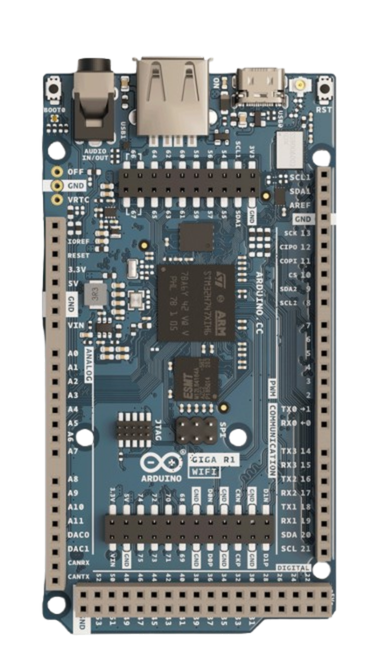
The Arduino Giga R1 WiFi is a powerful microcontroller board designed by Arduino for advanced IoT (Internet of Things) applications. It features built-in WiFi and Bluetooth connectivity, making it ideal for projects requiring wireless communication. With its high-performance processor, extensive I/O pins, and compatibility with a wide range of sensors and modules, the Giga R1 WiFi is suitable for both hobbyists and professionals.
Explore Projects Built with Arduino Giga R1 WiFi
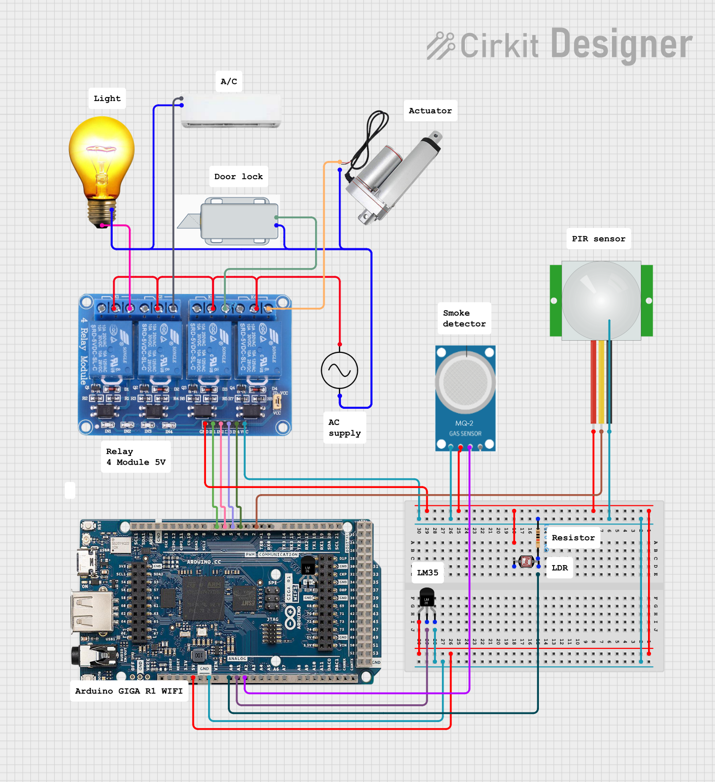
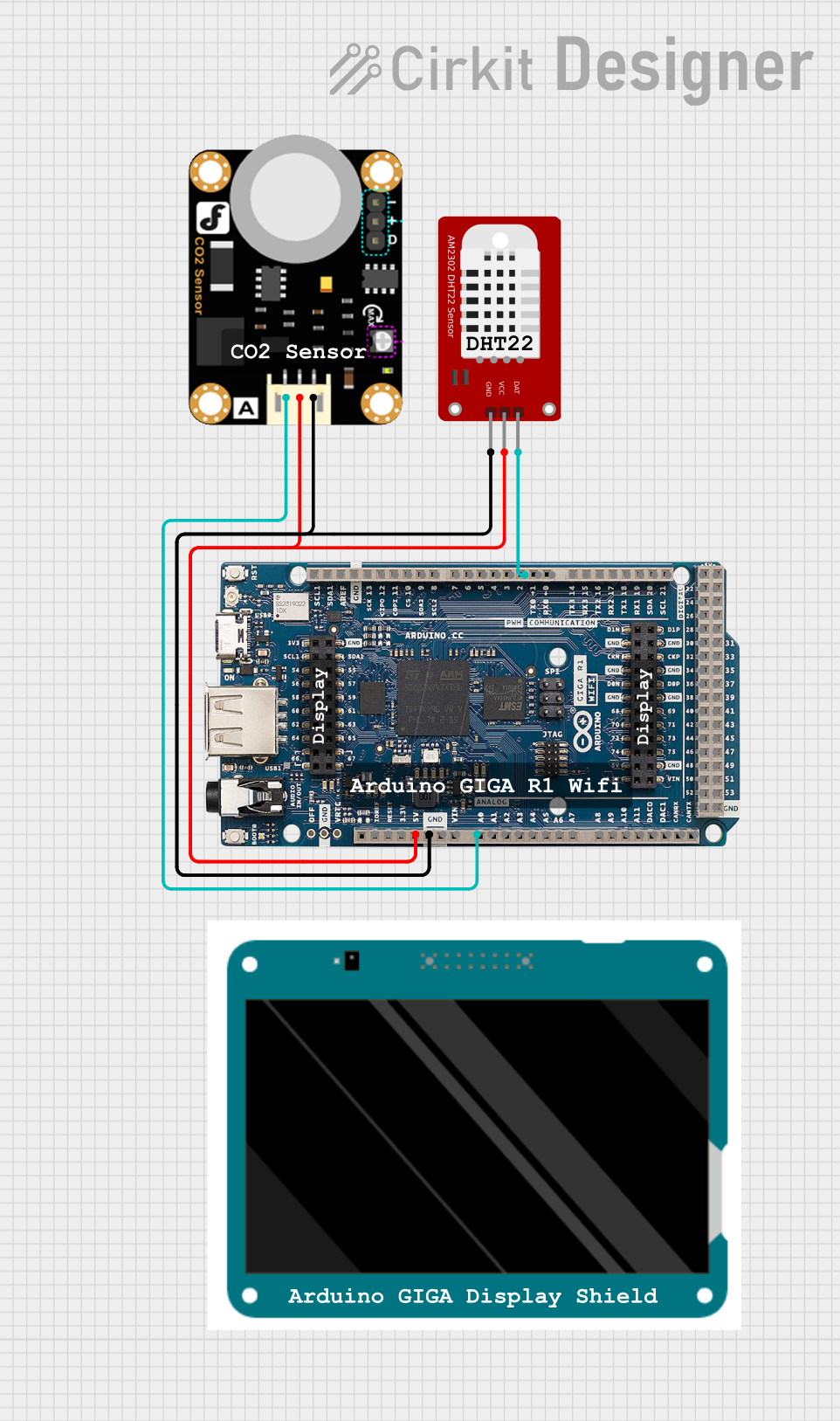
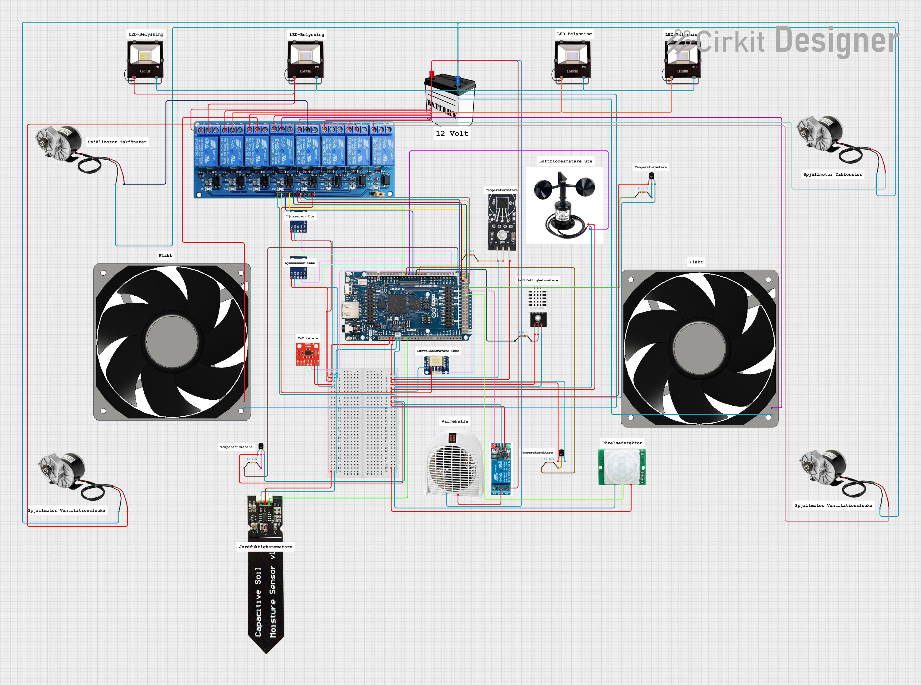
Explore Projects Built with Arduino Giga R1 WiFi
Common Applications and Use Cases
- IoT devices and smart home automation
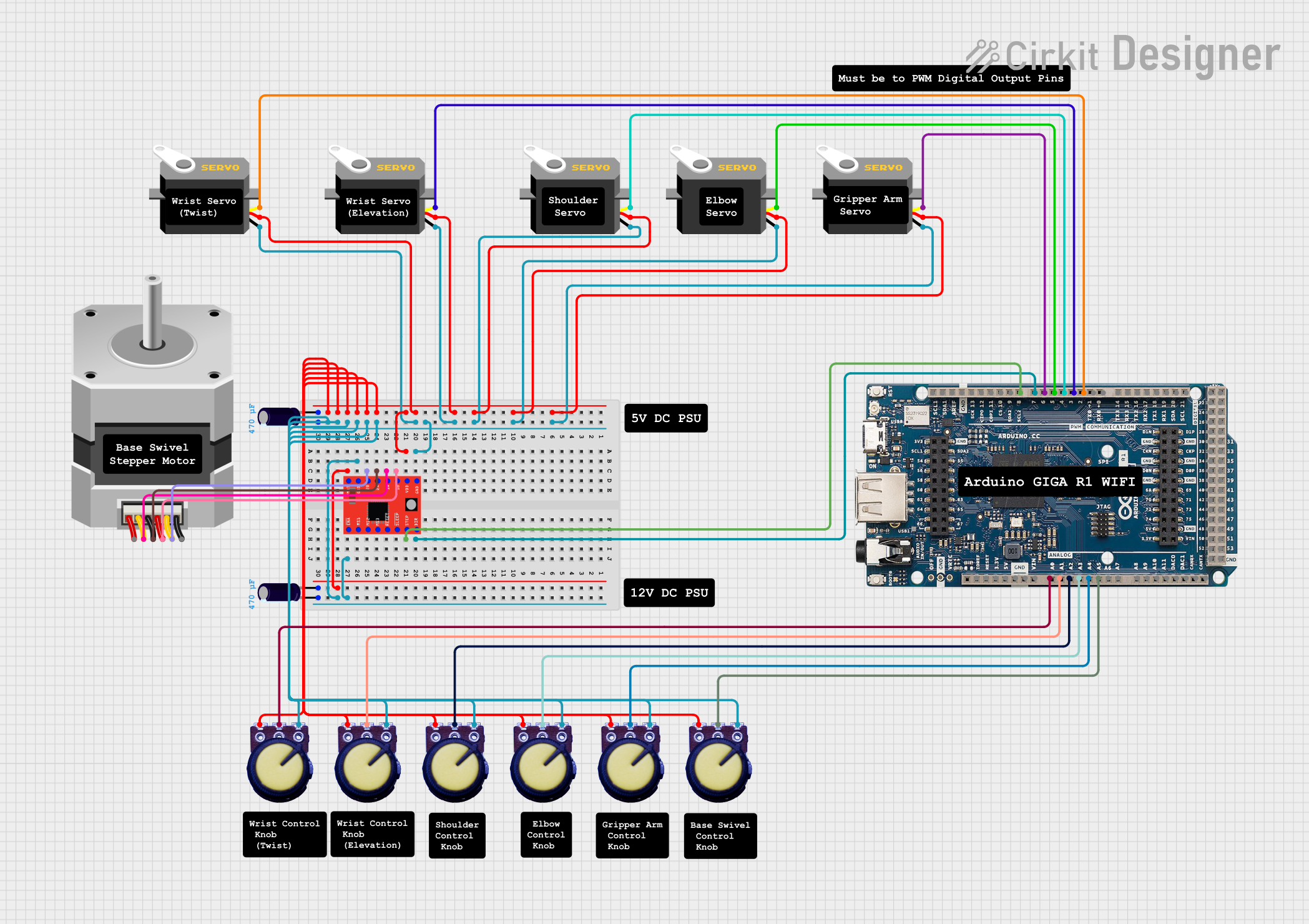
- Robotics and motor control
- Data logging and environmental monitoring
- Wireless communication and networking
- Prototyping advanced embedded systems
Technical Specifications
The following table outlines the key technical details of the Arduino Giga R1 WiFi:
| Specification | Details |
|---|---|
| Microcontroller | STM32H747XI dual-core (Cortex-M7 @ 480 MHz and Cortex-M4 @ 240 MHz) |
| Operating Voltage | 3.3V |
| Input Voltage (VIN) | 7-12V |
| Digital I/O Pins | 76 (12 of which support PWM) |
| Analog Input Pins | 12 |
| Analog Output Pins | 2 (DAC) |
| Flash Memory | 8 MB |
| SRAM | 1 MB |
| EEPROM | 16 KB |
| WiFi and Bluetooth | Integrated (based on Murata 1DX module) |
| USB Ports | USB-C (programming and power) and USB-A (host) |
| Communication Protocols | UART, I2C, SPI, CAN, Ethernet |
| Dimensions | 102 x 25 mm |
Pin Configuration and Descriptions
The Arduino Giga R1 WiFi has a rich set of pins for various functionalities. Below is a summary of the pin configuration:
| Pin | Function | Description |
|---|---|---|
| VIN | Power Input | External power supply input (7-12V). |
| 3.3V | Power Output | Regulated 3.3V output for external components. |
| GND | Ground | Common ground for the circuit. |
| Digital Pins | D0-D75 | General-purpose digital I/O pins. |
| PWM Pins | D2, D3, D5, D6, D9, D10, D11, etc. | Digital pins with PWM functionality. |
| Analog Pins | A0-A11 | Analog input pins (12-bit ADC). |
| DAC Pins | DAC0, DAC1 | Analog output pins (10-bit DAC). |
| I2C | SDA, SCL | I2C communication pins. |
| SPI | SCK, MISO, MOSI, SS | SPI communication pins. |
| UART | TX, RX | Serial communication pins. |
| USB-C | USB Power/Programming | USB-C port for programming and power. |
| USB-A | USB Host | USB-A port for connecting peripherals. |
Usage Instructions
How to Use the Arduino Giga R1 WiFi in a Circuit
Powering the Board:
- Use the USB-C port to power the board via a computer or USB adapter.
- Alternatively, connect an external power supply (7-12V) to the VIN pin.
Programming the Board:
- Install the Arduino IDE (version 2.0 or later) on your computer.
- Connect the board to your computer using a USB-C cable.
- Select "Arduino Giga R1 WiFi" from the Tools > Board menu in the IDE.
- Write your code and upload it to the board.
Connecting Sensors and Modules:
- Use the digital and analog pins to connect sensors, actuators, and other modules.
- Ensure proper voltage levels (3.3V) to avoid damaging the board.
Using WiFi and Bluetooth:
- Use the built-in WiFi and Bluetooth capabilities for wireless communication.
- Libraries such as
WiFi.handBluetoothSerial.hcan be used for programming.
Important Considerations and Best Practices
- Voltage Levels: The board operates at 3.3V logic levels. Avoid connecting 5V signals directly to the pins.
- Power Supply: Ensure a stable power supply to avoid unexpected resets or malfunctions.
- Heat Management: The STM32H747XI microcontroller can get warm during operation. Ensure proper ventilation.
- Firmware Updates: Regularly check for firmware updates to ensure optimal performance and compatibility.
Example Code: Connecting to WiFi
Below is an example sketch to connect the Arduino Giga R1 WiFi to a WiFi network:
#include <WiFi.h> // Include the WiFi library

const char* ssid = "Your_SSID";       // Replace with your WiFi network name
const char* password = "Your_Password"; // Replace with your WiFi password

void setup() {
  Serial.begin(115200); // Initialize serial communication at 115200 baud
  Serial.println("Connecting to WiFi...");

  WiFi.begin(ssid, password); // Start WiFi connection

  while (WiFi.status() != WL_CONNECTED) {
    delay(1000); // Wait for connection
    Serial.println("Attempting to connect...");
  }

  Serial.println("Connected to WiFi!");
  Serial.print("IP Address: ");
  Serial.println(WiFi.localIP()); // Print the assigned IP address
}

void loop() {
  // Add your main code here
}
Troubleshooting and FAQs
Common Issues and Solutions
Board Not Detected by Arduino IDE:
- Ensure the correct USB-C cable is used (data-capable, not just for charging).
- Verify that the correct board is selected in the Tools > Board menu.
- Install the necessary drivers if prompted by your operating system.
WiFi Connection Fails:
- Double-check the SSID and password for typos.
- Ensure the WiFi network is operational and within range.
- Restart the board and try reconnecting.
Program Upload Fails:
- Press the reset button on the board and try uploading again.
- Check for conflicting serial ports and close other applications using the port.
FAQs
Q: Can I use 5V sensors with the Giga R1 WiFi?
A: The board operates at 3.3V logic levels. Use a level shifter to interface with 5V sensors.
Q: How do I update the firmware?
A: Use the Arduino IDE or the STM32CubeProgrammer tool to update the firmware. Follow the instructions provided on the Arduino website.
Q: Is the Giga R1 WiFi compatible with Arduino shields?
A: Yes, it is compatible with most Arduino shields, but ensure they support 3.3V logic levels.
Q: Can I use the USB-A port for data transfer?
A: The USB-A port is designed for connecting peripherals like keyboards, mice, or USB drives, not for programming the board.
This concludes the documentation for the Arduino Giga R1 WiFi. For further assistance, refer to the official Arduino website or community forums.