How to Use DC Motor with Encoder: Examples, Pinouts, and Specs
Introduction
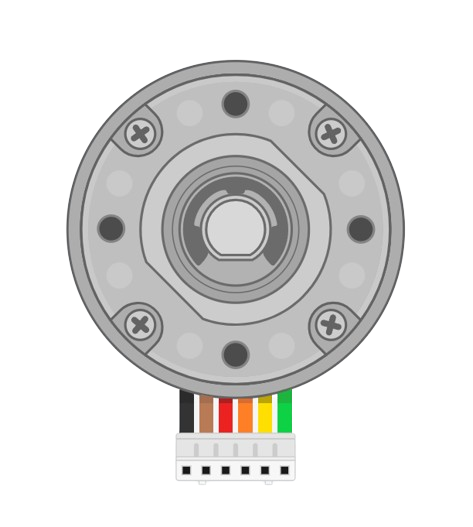
A DC motor with an encoder is a precision device that combines the functionality of a direct current (DC) motor with a rotary encoder. This combination allows for the precise control of the motor's position, speed, and acceleration. Common applications include robotics, automated machinery, and any system requiring accurate motion control.
Explore Projects Built with DC Motor with Encoder

Explore Projects Built with DC Motor with Encoder
Technical Specifications
General Specifications
- Operating Voltage: Typically ranges from 3V to 24V
- Rated Current: Varies with motor size and construction
- Output Power: Depends on motor rating
- Encoder Type: Incremental or Absolute
- Encoder Resolution: Specified in pulses per revolution (PPR)
Pin Configuration and Descriptions
| Pin Number | Description | Notes |
|---|---|---|
| 1 | Motor Power (+) | Connect to motor power supply |
| 2 | Motor Power (-) | Connect to ground |
| 3 | Encoder Vcc | Encoder power supply (3.3V/5V) |
| 4 | Encoder GND | Ground for encoder |
| 5 | Encoder Output A | Signal A output |
| 6 | Encoder Output B | Signal B output (optional) |
| 7 | Encoder Index | Index pulse (optional) |
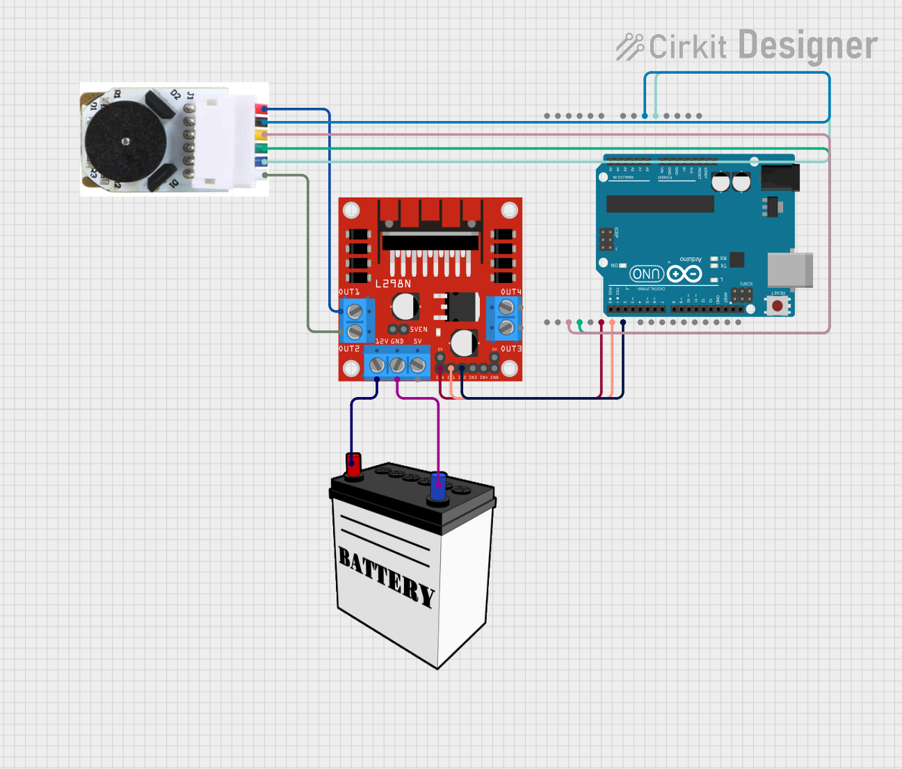
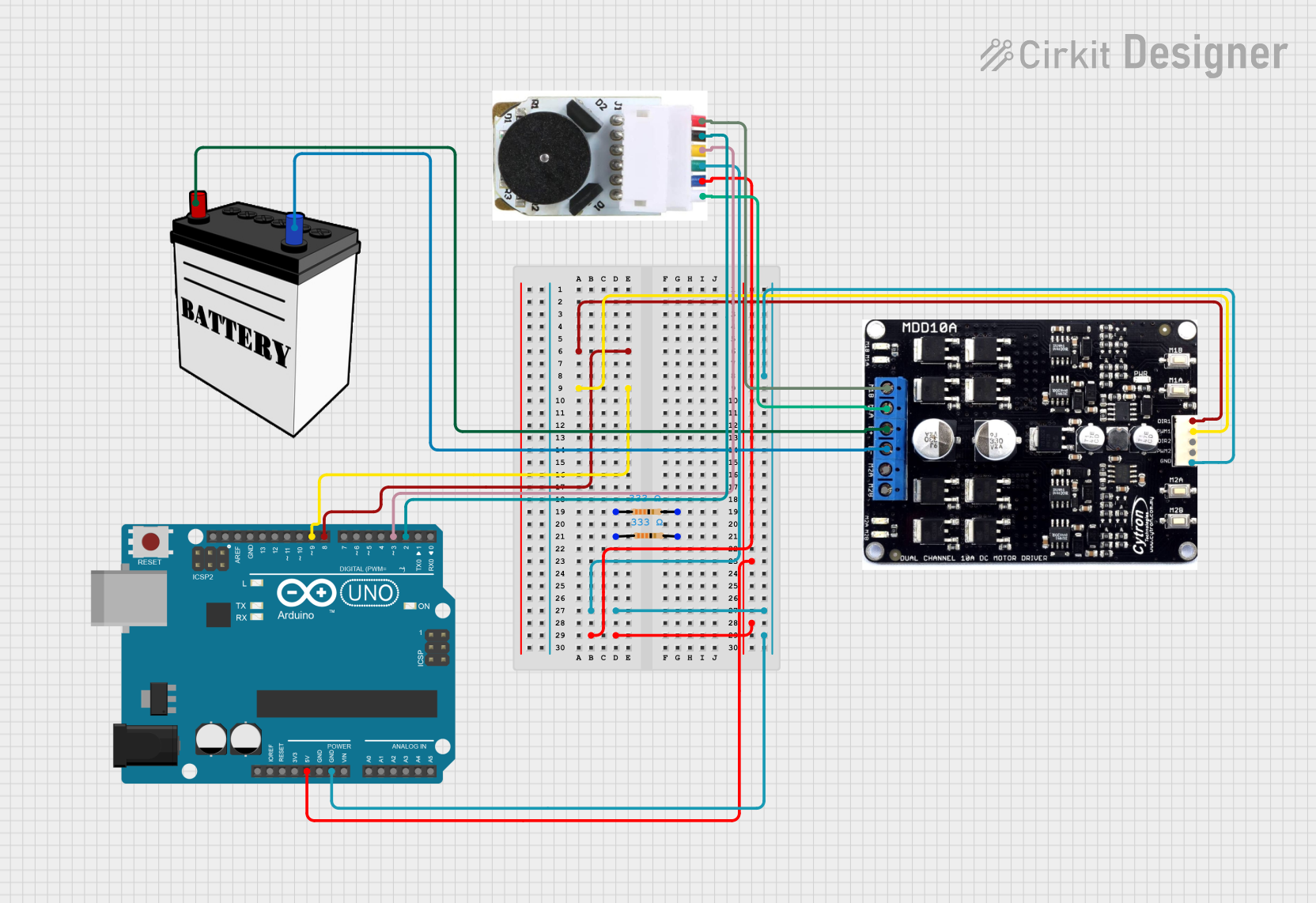
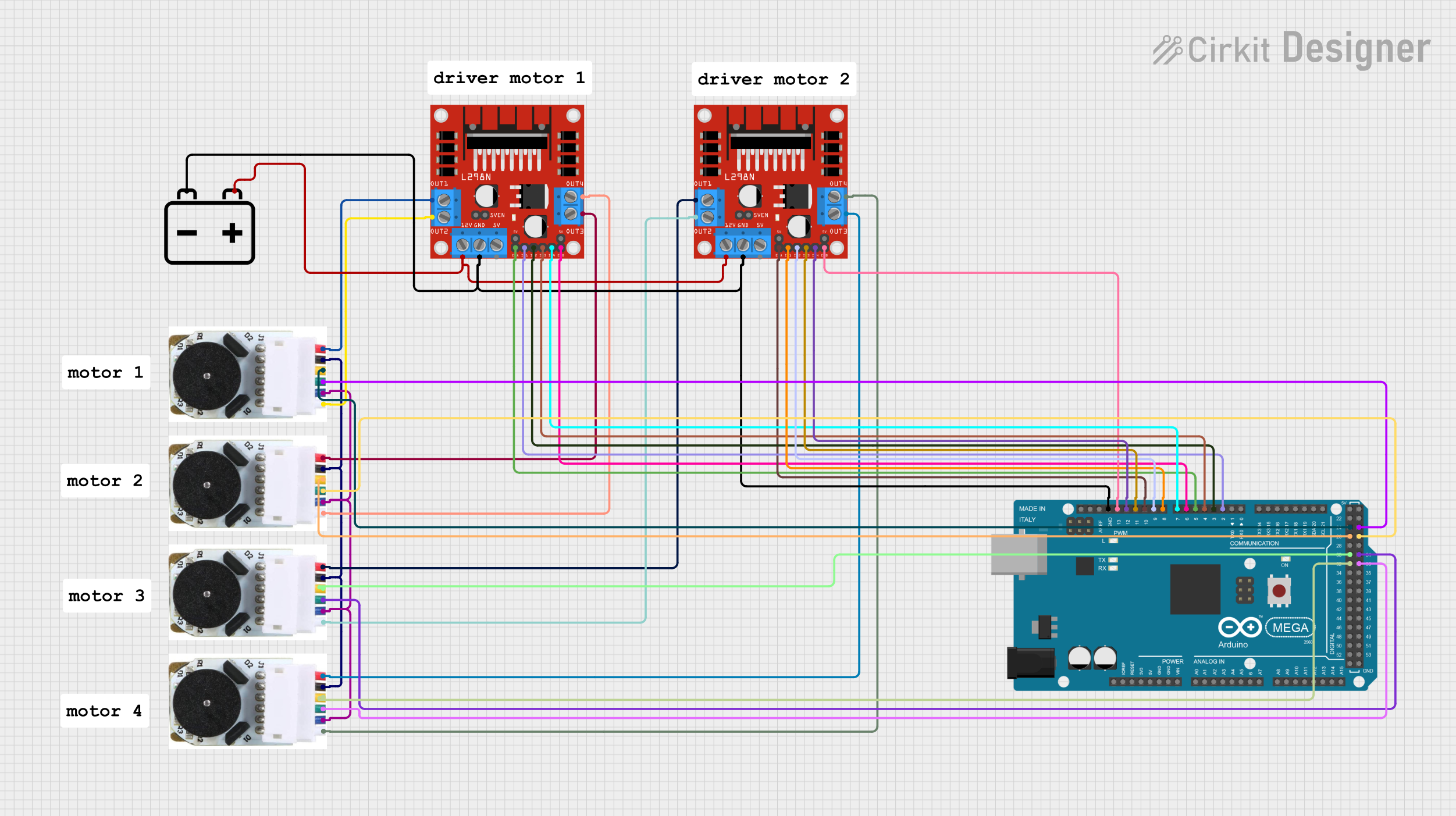
Usage Instructions
Connecting the Motor
- Connect the motor power pins to your power supply, ensuring the voltage matches the motor's specifications.
- Ground the motor power (-) to the common ground in your circuit.
Interfacing with an Encoder
- Connect the encoder Vcc to a 3.3V or 5V power supply, depending on the encoder's requirements.
- Ground the encoder GND to the common ground.
- Connect the encoder outputs A (and B, if available) to the digital input pins on your microcontroller.
Best Practices
- Use a motor driver between the motor and your control circuit to handle the current and protect your microcontroller.
- Implement proper debouncing for the encoder signals to ensure accurate readings.
- Use pull-up or pull-down resistors on the encoder outputs if required by your microcontroller.
Example Code for Arduino UNO
// Define motor and encoder pins
const int motorPin1 = 3; // Motor pin 1
const int motorPin2 = 4; // Motor pin 2
const int encoderPinA = 2; // Encoder output A

// Variables to hold encoder position
volatile long encoderPos = 0;

// Interrupt service routine for encoder A
void encoderA_ISR() {
  // Change in encoder position - adjust as necessary based on motor direction
  encoderPos++;
}

void setup() {
  // Set motor pins as outputs
  pinMode(motorPin1, OUTPUT);
  pinMode(motorPin2, OUTPUT);

  // Set encoder pin as input
  pinMode(encoderPinA, INPUT_PULLUP);

  // Attach interrupt for the encoder pin A
  attachInterrupt(digitalPinToInterrupt(encoderPinA), encoderA_ISR, RISING);

  // Start the motor
  analogWrite(motorPin1, 128); // Set speed (0-255)
  digitalWrite(motorPin2, LOW); // Set direction
}

void loop() {
  // The main loop of the program
  // Use encoderPos to control or monitor the motor position
}
Troubleshooting and FAQs
Common Issues
- Motor not turning: Check power supply and connections. Ensure the motor driver is functioning.
- Inaccurate encoder readings: Verify the encoder connections and ensure proper debouncing.
- Motor stalling: Ensure the power supply can provide sufficient current for the motor.
FAQs
Q: How do I reverse the motor direction? A: Reverse the polarity of the motor connections or control the motor driver's direction pin.
Q: What is the purpose of the encoder index pulse? A: The index pulse is a reference signal used to establish a known position for the motor.
Q: Can I use this motor with a 3.3V system? A: Yes, but ensure the encoder is compatible with 3.3V and use a motor driver that supports 3.3V logic levels.
Remember to always refer to the specific datasheet of your DC motor with encoder for precise specifications and connection details.