How to Use Adafruit TFT 1.8 inch 160x128 w microSD: Examples, Pinouts, and Specs
Introduction
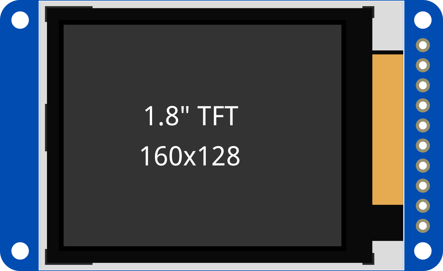
The Adafruit TFT 1.8 inch 160x128 with microSD card slot is a versatile and compact color display module suitable for a wide range of electronics projects. With its 1.8-inch diagonal screen and 160x128 pixel resolution, it provides a clear and colorful interface for user interaction. The integrated microSD card slot allows for additional storage capacity, making it ideal for displaying images, videos, or storing other data. Common applications include handheld devices, DIY game consoles, and interactive displays.
Explore Projects Built with Adafruit TFT 1.8 inch 160x128 w microSD


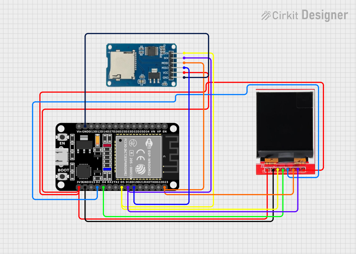
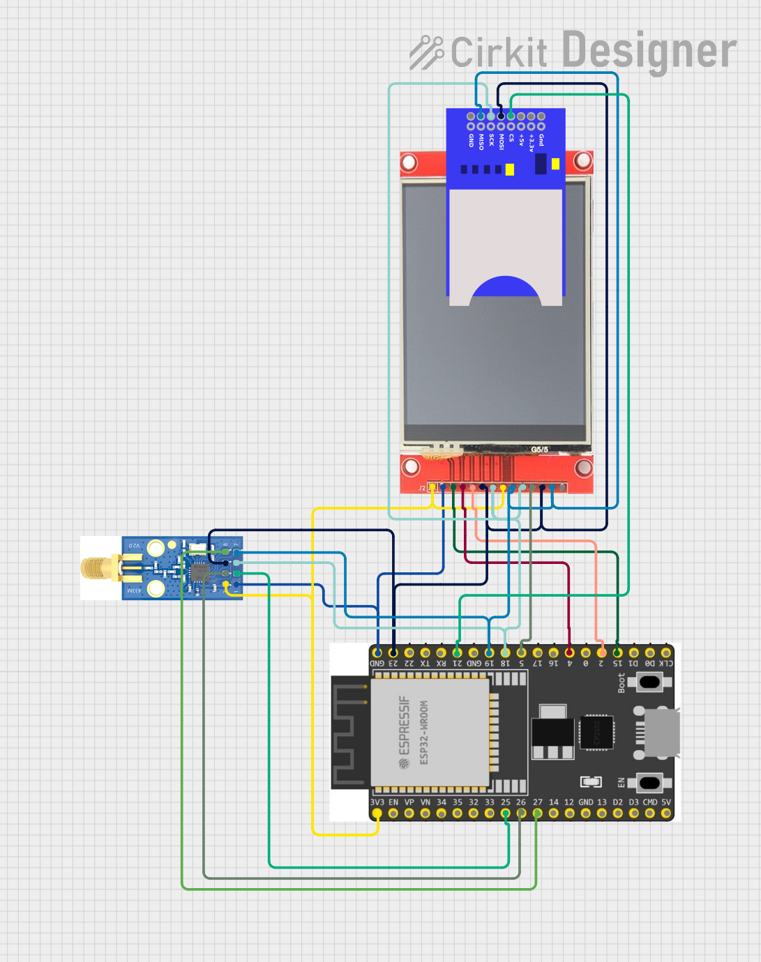
Explore Projects Built with Adafruit TFT 1.8 inch 160x128 w microSD
Technical Specifications
General Features
- Display Size: 1.8 inches diagonal
- Resolution: 160x128 pixels
- Color Depth: 18-bit (262,144 colors)
- Interface: SPI (Serial Peripheral Interface)
- Onboard microSD card slot for additional storage
- 4-wire resistive touch screen (optional, not included in all models)
Electrical Characteristics
- Operating Voltage: 3.3V to 5V
- Logic Level: 3.3V (5V tolerant)
- Maximum Current Draw: 50mA (without microSD card)
Pin Configuration and Descriptions
| Pin Number | Name | Description |
|---|---|---|
| 1 | VCC | Power supply (3.3V-5V) |
| 2 | GND | Ground connection |
| 3 | CS | Chip Select for the TFT display |
| 4 | RESET | Reset pin for the display |
| 5 | D/C | Data/Command control pin |
| 6 | MOSI | Master Out Slave In for SPI |
| 7 | SCK | Serial Clock for SPI |
| 8 | MISO | Master In Slave Out for SPI (optional for display, used for microSD) |
| 9 | LED | Backlight control pin (can be connected to PWM for brightness control) |
| 10 | CARD_CS | Chip Select for the microSD card slot |
Usage Instructions
Connecting to an Arduino UNO
Connect the display pins to the corresponding Arduino pins as follows:
- VCC to 5V (or 3.3V if available)
- GND to GND
- CS to digital pin 10
- RESET to digital pin 9
- D/C to digital pin 8
- MOSI to digital pin 11
- SCK to digital pin 13
- LED to digital pin 6 (for PWM brightness control)
- CARD_CS to digital pin 4 (for microSD card usage)
If you are using the microSD card slot, connect MISO to digital pin 12.
Programming the Display
To control the display, you will need to use the Adafruit GFX and ST7735 libraries, which can be installed through the Arduino Library Manager.
#include <Adafruit_GFX.h>    // Core graphics library
#include <Adafruit_ST7735.h> // Hardware-specific library for ST7735
#include <SPI.h>

// Pin definitions
#define TFT_CS     10
#define TFT_RST    9
#define TFT_DC     8
#define SD_CS      4

// Initialize Adafruit ST7735 TFT library
Adafruit_ST7735 tft = Adafruit_ST7735(TFT_CS, TFT_DC, TFT_RST);

void setup() {
  Serial.begin(9600);
  tft.initR(INITR_BLACKTAB);      // Initialize display with black tab
  tft.fillScreen(ST7735_BLACK);   // Clear screen with black color
}

void loop() {
  // Your code to interact with the display goes here
}
Best Practices
- Always use a level shifter or logic level converter if you are interfacing with a 5V microcontroller to ensure the longevity of the display.
- Use a current limiting resistor if you are controlling the backlight LED directly.
- When writing to the microSD card, ensure that you are using the correct file formats and handling file operations properly to prevent data corruption.
Troubleshooting and FAQs
Common Issues
- Display not powering on: Check the connections, especially VCC and GND. Ensure that the power supply is within the specified range.
- White screen or no image: Verify that the SPI connections are correct and that the correct pins are defined in your code.
- SD card not recognized: Ensure that the microSD card is formatted correctly (FAT16/FAT32) and that the CARD_CS pin is connected and defined properly in your code.
FAQs
Q: Can I use this display with a 5V microcontroller? A: Yes, the display is 5V tolerant, but it is recommended to use a level shifter for safer operation.
Q: How do I adjust the brightness of the backlight? A: Connect the LED pin to a PWM-capable pin on your microcontroller and use analogWrite() to adjust the brightness.
Q: What is the maximum size of microSD card supported? A: The display supports microSD cards up to 32GB formatted with FAT16 or FAT32 file system.
For further assistance, consult the Adafruit forums or the community resources available for the Adafruit TFT 1.8 inch 160x128 display.