How to Use EGT Sensors: Examples, Pinouts, and Specs
Introduction
Exhaust Gas Temperature (EGT) Sensors are precision devices designed to measure the temperature of exhaust gases in internal combustion engines. These sensors play a critical role in monitoring engine performance, optimizing fuel efficiency, and ensuring compliance with emissions regulations. By providing real-time temperature data, EGT sensors help prevent engine damage caused by excessive heat and enable fine-tuning of engine parameters for improved performance.
Explore Projects Built with EGT Sensors
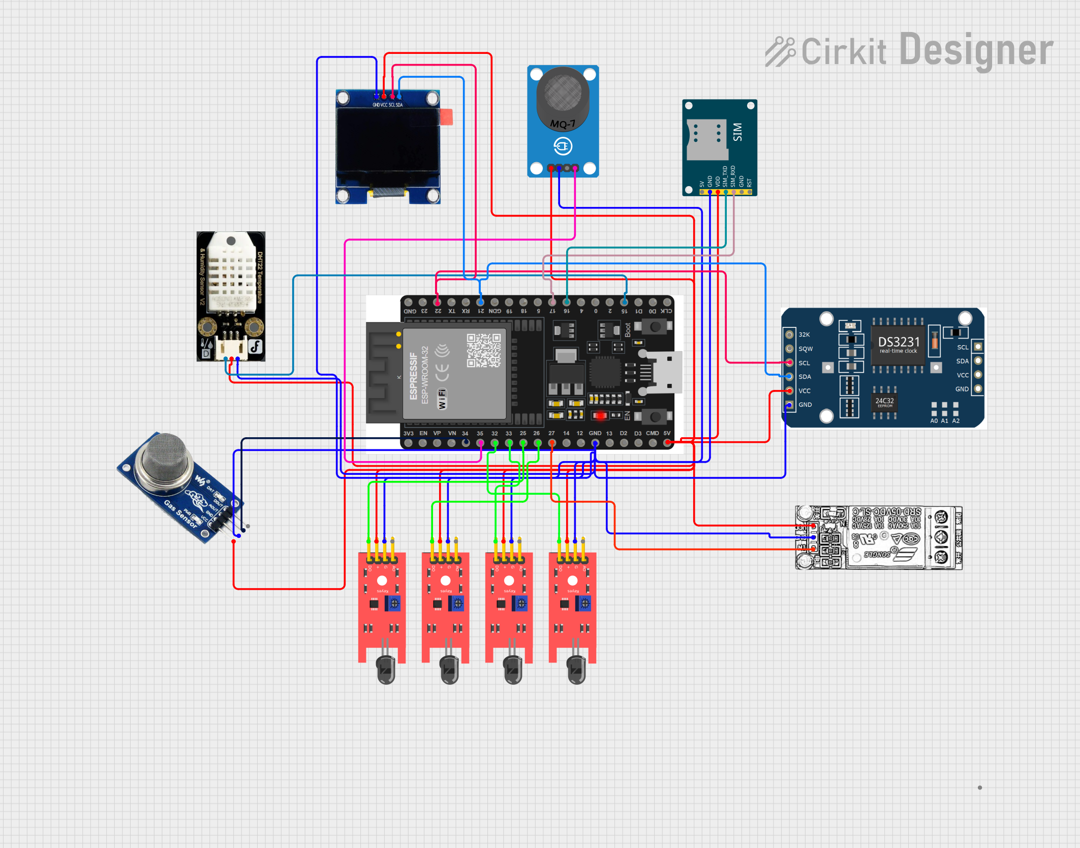
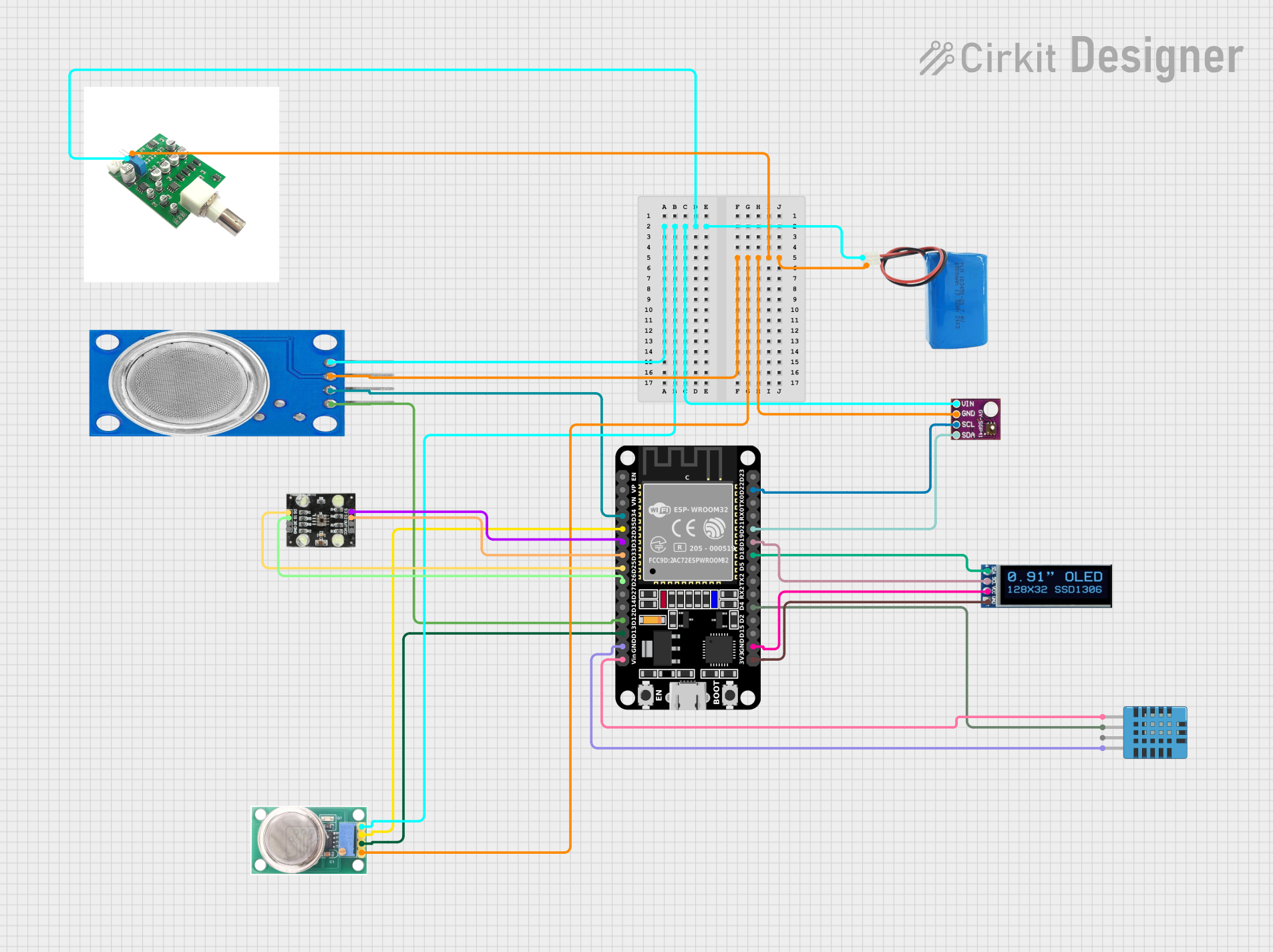
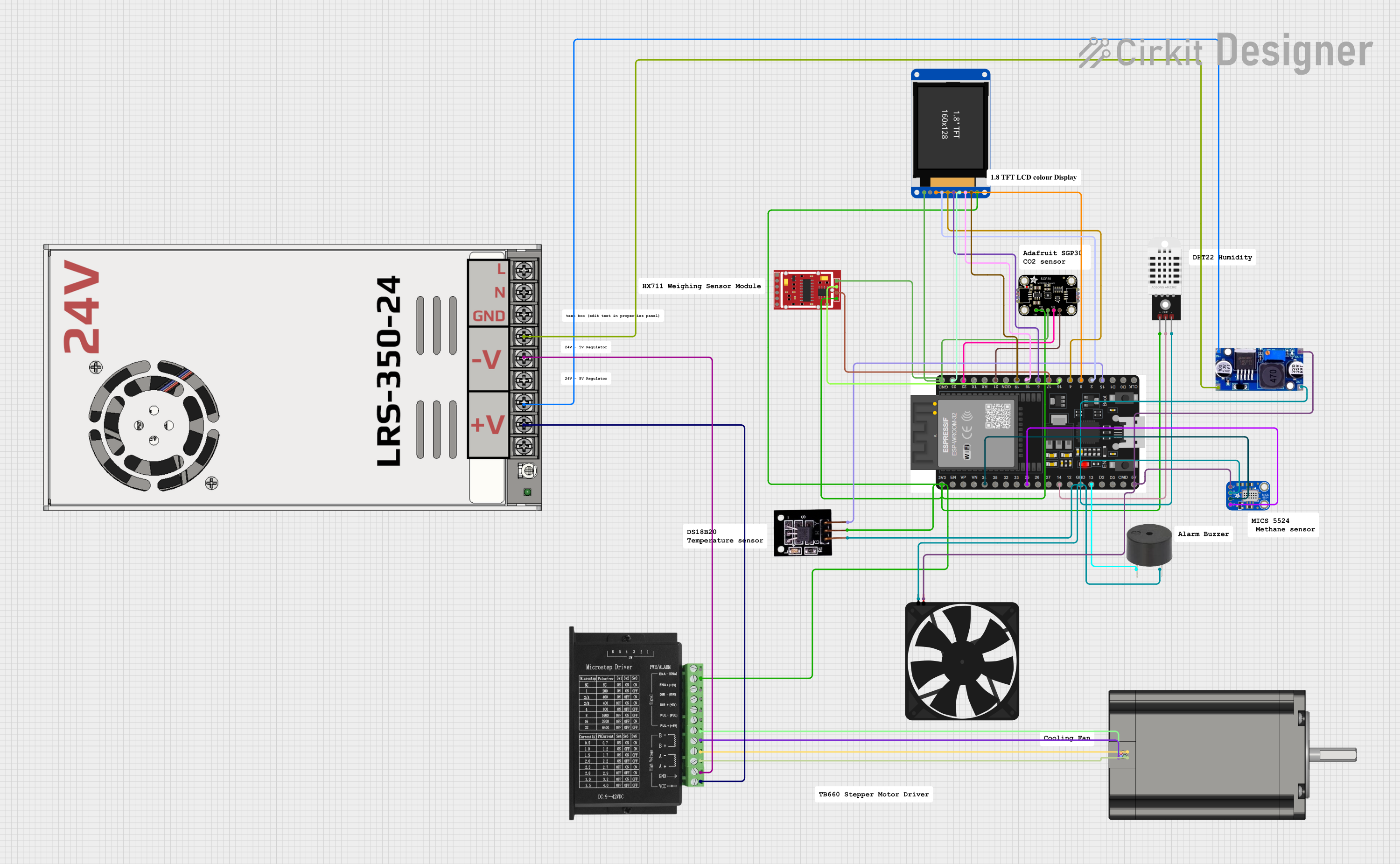
Explore Projects Built with EGT Sensors
Common Applications and Use Cases
- Automotive engines for performance tuning and emissions control
- Aircraft engines for monitoring exhaust gas temperatures
- Industrial machinery and power generation systems
- Marine engines for thermal management
- Turbocharged engines to prevent overheating and optimize boost levels
Technical Specifications
Below are the key technical details for the EGT sensor manufactured by EGT, with part ID: EGT.
General Specifications
- Measurement Range: -40°C to 1,200°C (-40°F to 2,192°F)
- Accuracy: ±1% of the measured value
- Response Time: < 100 ms
- Output Signal: Millivolt signal (typical for thermocouples, e.g., Type K)
- Operating Voltage: N/A (passive sensor, requires external amplifier)
- Connector Type: Standard thermocouple connectors or custom harness
- Material: Stainless steel probe with ceramic insulation
- Probe Length: 50 mm to 200 mm (varies by model)
- Thread Size: M8 x 1.0 or M10 x 1.0 (varies by model)
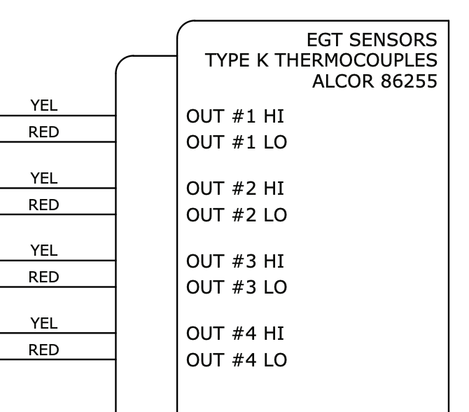
Pin Configuration and Descriptions
The EGT sensor typically uses a two-wire configuration for its thermocouple output. Below is the pinout description:
| Pin | Wire Color | Description |
|---|---|---|
| 1 | Yellow | Positive terminal (Type K thermocouple) |
| 2 | Red | Negative terminal (Type K thermocouple) |
Note: Wire colors may vary depending on the manufacturer or region. Always refer to the specific datasheet for your sensor model.
Usage Instructions
How to Use the EGT Sensor in a Circuit
- Connect the Sensor:
- Attach the yellow wire (positive) to the positive input of a thermocouple amplifier or ADC (Analog-to-Digital Converter).
- Attach the red wire (negative) to the ground or negative input of the amplifier/ADC.
- Amplify the Signal:
- Since the EGT sensor outputs a small millivolt signal, use a thermocouple amplifier (e.g., MAX31855 or AD8495) to amplify the signal for further processing.
- Read the Data:
- Connect the amplified signal to a microcontroller (e.g., Arduino UNO) to read and process the temperature data.
- Calibrate the Sensor:
- Perform calibration using known temperature points to ensure accurate readings.
- Install the Sensor:
- Mount the sensor in the exhaust manifold or downpipe using the appropriate thread size. Ensure the probe is securely fastened and exposed to the exhaust gas flow.
Important Considerations and Best Practices
- Placement: Install the sensor as close to the exhaust manifold as possible for accurate readings.
- Heat Protection: Use heat-resistant wiring and connectors to prevent damage from high temperatures.
- Signal Noise: Minimize electrical noise by using shielded cables and proper grounding.
- Amplifier Selection: Choose an amplifier compatible with the thermocouple type (e.g., Type K).
- Avoid Over-Tightening: When installing the sensor, avoid over-tightening to prevent damage to the threads or probe.
Example Code for Arduino UNO
Below is an example of how to interface an EGT sensor with an Arduino UNO using a MAX31855 thermocouple amplifier:
#include <Adafruit_MAX31855.h>

// Define the pins for the MAX31855 amplifier
#define DO_PIN 3  // Data Out pin
#define CS_PIN 4  // Chip Select pin
#define CLK_PIN 5 // Clock pin

// Create an instance of the MAX31855 library
Adafruit_MAX31855 thermocouple(CLK_PIN, CS_PIN, DO_PIN);

void setup() {
  Serial.begin(9600);
  Serial.println("EGT Sensor Test");

  // Check if the thermocouple amplifier is connected
  if (!thermocouple.begin()) {
    Serial.println("Error: MAX31855 not detected. Check wiring!");
    while (1);
  }
}

void loop() {
  // Read the temperature in Celsius
  double temperature = thermocouple.readCelsius();

  // Check for errors
  if (isnan(temperature)) {
    Serial.println("Error: Failed to read temperature!");
  } else {
    // Print the temperature to the Serial Monitor
    Serial.print("Exhaust Gas Temperature: ");
    Serial.print(temperature);
    Serial.println(" °C");
  }

  delay(1000); // Wait 1 second before the next reading
}
Note: Ensure the MAX31855 library is installed in your Arduino IDE. You can install it via the Library Manager.
Troubleshooting and FAQs
Common Issues and Solutions
No Signal or Incorrect Readings
- Cause: Loose or incorrect wiring.
- Solution: Verify the connections between the sensor, amplifier, and microcontroller. Ensure the positive and negative terminals are correctly connected.
Fluctuating or Noisy Readings
- Cause: Electrical noise or poor grounding.
- Solution: Use shielded cables and ensure proper grounding of the circuit.
Sensor Overheating
- Cause: Installed too close to the exhaust port or in an area with excessive heat.
- Solution: Reposition the sensor to a location within its operating temperature range.
Amplifier Not Detected
- Cause: Faulty amplifier or incorrect wiring.
- Solution: Check the amplifier connections and ensure it is powered correctly.
FAQs
Q1: Can I use the EGT sensor with other microcontrollers besides Arduino?
A1: Yes, the EGT sensor can be used with any microcontroller that supports thermocouple amplifiers, such as Raspberry Pi, ESP32, or STM32.
Q2: How do I clean the EGT sensor?
A2: Use a soft cloth and a mild cleaning solution to remove soot or debris. Avoid abrasive materials that could damage the probe.
Q3: What happens if the sensor is exposed to temperatures beyond its range?
A3: Prolonged exposure to extreme temperatures may damage the sensor or reduce its accuracy. Always operate within the specified range.
Q4: Can I extend the sensor wires?
A4: Yes, but use thermocouple extension wires of the same type (e.g., Type K) to maintain accuracy.
By following this documentation, you can effectively integrate and troubleshoot EGT sensors in your projects.