
How to Use VRM: Examples, Pinouts, and Specs

 Design with VRM in Cirkit Designer
Introduction
A Voltage Regulator Module (VRM) is an electronic device designed to convert a higher input voltage to a lower, stable output voltage. It ensures that sensitive components, such as CPUs, GPUs, and other integrated circuits, receive a consistent and reliable power supply. VRMs are critical in modern electronics, particularly in computing systems, where they help maintain performance and prevent damage caused by voltage fluctuations.
Explore Projects Built with VRM
 Open Project in Cirkit Designer
 Open Project in Cirkit Designer
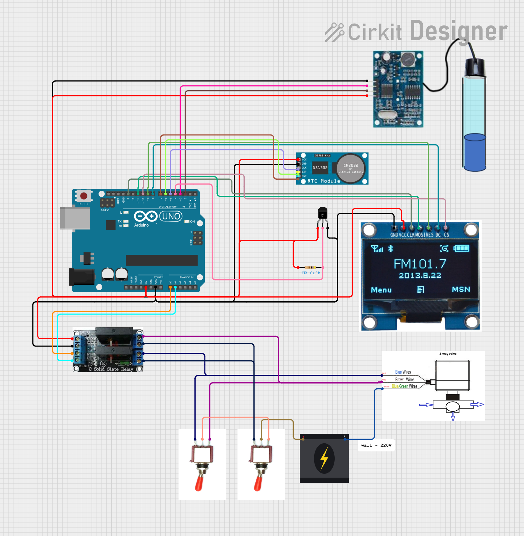 Open Project in Cirkit Designer
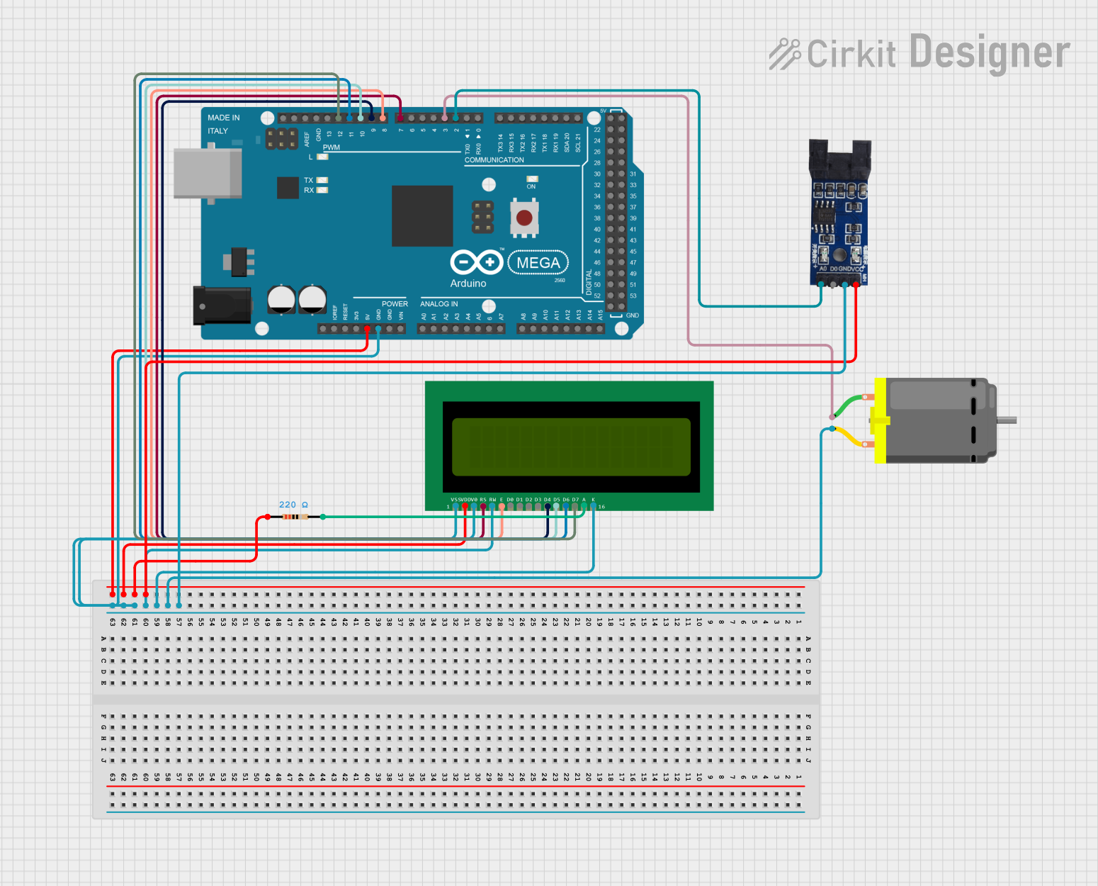 Open Project in Cirkit Designer
Explore Projects Built with VRM
Open Project in Cirkit DesignerOpen Project in Cirkit DesignerOpen Project in Cirkit DesignerOpen Project in Cirkit DesignerCommon Applications and Use Cases
- Powering CPUs and GPUs in computers and servers
- Voltage regulation in motherboards and graphics cards
- Power management in embedded systems
- Use in telecommunications and networking equipment
- Industrial automation and robotics
Technical Specifications
Key Technical Details
- Input Voltage Range: Typically 5V to 24V (varies by model)
- Output Voltage: Adjustable or fixed, commonly 1.0V to 12V
- Output Current: Up to 50A or more, depending on the VRM design
- Efficiency: 85% to 95% (depending on load and design)
- Switching Frequency: 100 kHz to 1 MHz
- Thermal Protection: Over-temperature shutdown
- Overcurrent Protection: Built-in to prevent damage
- Form Factor: Compact, often integrated into PCBs
Pin Configuration and Descriptions
Below is a typical pin configuration for a VRM module. Note that the exact pinout may vary depending on the specific model.
| Pin Name | Description |
|---|---|
| VIN | Input voltage pin. Connects to the higher voltage source (e.g., 12V or 24V). |
| VOUT | Output voltage pin. Provides the regulated lower voltage to the load. |
| GND | Ground pin. Common ground for input and output. |
| EN (Enable) | Enable pin. Used to turn the VRM on or off. Active high in most designs. |
| FB (Feedback) | Feedback pin. Used to monitor and adjust the output voltage. |
| PG (Power Good) | Indicates whether the output voltage is within the specified range. |
Usage Instructions
How to Use the Component in a Circuit
Connect the Input Voltage:
- Attach the VIN pin to a DC power source within the VRM's input voltage range.
- Ensure the power source can supply sufficient current for the load.
Connect the Output Voltage:
- Connect the VOUT pin to the load that requires a regulated voltage.
- Verify that the load's current requirements do not exceed the VRM's maximum output current.
Ground Connections:
- Connect the GND pin to the common ground of the circuit.
Enable the VRM:
- If the VRM has an EN pin, ensure it is pulled high (e.g., connect to VIN) to enable the module.
Adjust Output Voltage (if applicable):
- For adjustable VRMs, use a potentiometer or resistor divider connected to the FB pin to set the desired output voltage.
Monitor Power Good Signal:
- Use the PG pin to monitor the status of the output voltage. A high signal typically indicates that the output is stable.
Important Considerations and Best Practices
- Heat Dissipation: VRMs can generate significant heat under high loads. Use adequate heat sinks or active cooling to prevent overheating.
- Input Capacitors: Place low-ESR capacitors near the VIN pin to reduce input voltage ripple.
- Output Capacitors: Use appropriate capacitors at the VOUT pin to stabilize the output voltage.
- Avoid Overloading: Ensure the load does not exceed the VRM's maximum current rating.
- PCB Layout: Minimize the length of high-current traces and use wide traces to reduce resistance and heat.
Example: Using a VRM with an Arduino UNO
Below is an example of how to use a VRM to power an Arduino UNO with a 5V regulated output.
Circuit Connections
- Connect a 12V DC power source to the VIN pin of the VRM.
- Set the VRM output to 5V using the FB pin (if adjustable).
- Connect the VOUT pin of the VRM to the 5V pin of the Arduino UNO.
- Connect the GND pin of the VRM to the GND pin of the Arduino UNO.
Sample Code
// Example code to blink an LED connected to pin 13 of the Arduino UNO
// Ensure the Arduino is powered via the VRM's regulated 5V output.

void setup() {
  pinMode(13, OUTPUT); // Set pin 13 as an output
}

void loop() {
  digitalWrite(13, HIGH); // Turn the LED on
  delay(1000);            // Wait for 1 second
  digitalWrite(13, LOW);  // Turn the LED off
  delay(1000);            // Wait for 1 second
}
Troubleshooting and FAQs
Common Issues and Solutions
VRM Overheating:
- Cause: Insufficient cooling or excessive load.
- Solution: Add a heat sink or fan. Reduce the load current.
Output Voltage Not Stable:
- Cause: Insufficient input or output capacitors.
- Solution: Add low-ESR capacitors near the VIN and VOUT pins.
No Output Voltage:
- Cause: EN pin not connected or pulled low.
- Solution: Ensure the EN pin is pulled high to enable the VRM.
Power Good Signal Not High:
- Cause: Output voltage is out of range.
- Solution: Check the load and ensure it is within the VRM's specifications.
FAQs
Can I use a VRM with an AC power source? No, VRMs are designed for DC input only. Use an AC-to-DC converter before the VRM.
What happens if I exceed the VRM's maximum current rating? Exceeding the current rating can cause overheating, voltage instability, or permanent damage to the VRM.
Can I use a VRM to power multiple devices? Yes, as long as the total current draw of all devices does not exceed the VRM's maximum output current.
How do I select the right VRM for my application? Consider the input voltage range, output voltage, maximum current, efficiency, and thermal performance when selecting a VRM.