
How to Use Adafruit 2.13in eInk Breakout Rev D: Examples, Pinouts, and Specs
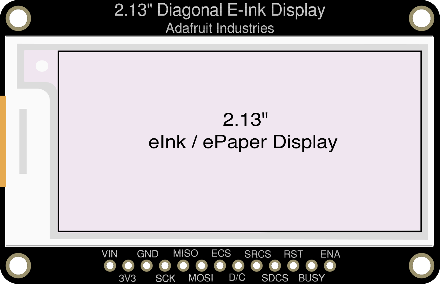
 Design with Adafruit 2.13in eInk Breakout Rev D in Cirkit Designer
Introduction
The Adafruit 2.13in eInk Breakout Rev D (Part ID: 6366) is a compact display module featuring a 2.13-inch eInk screen. This module is designed for low-power applications and provides excellent contrast and visibility, even in bright sunlight. Its ability to retain an image without power makes it ideal for projects requiring static images or text, such as electronic labels, dashboards, and IoT displays.
Explore Projects Built with Adafruit 2.13in eInk Breakout Rev D
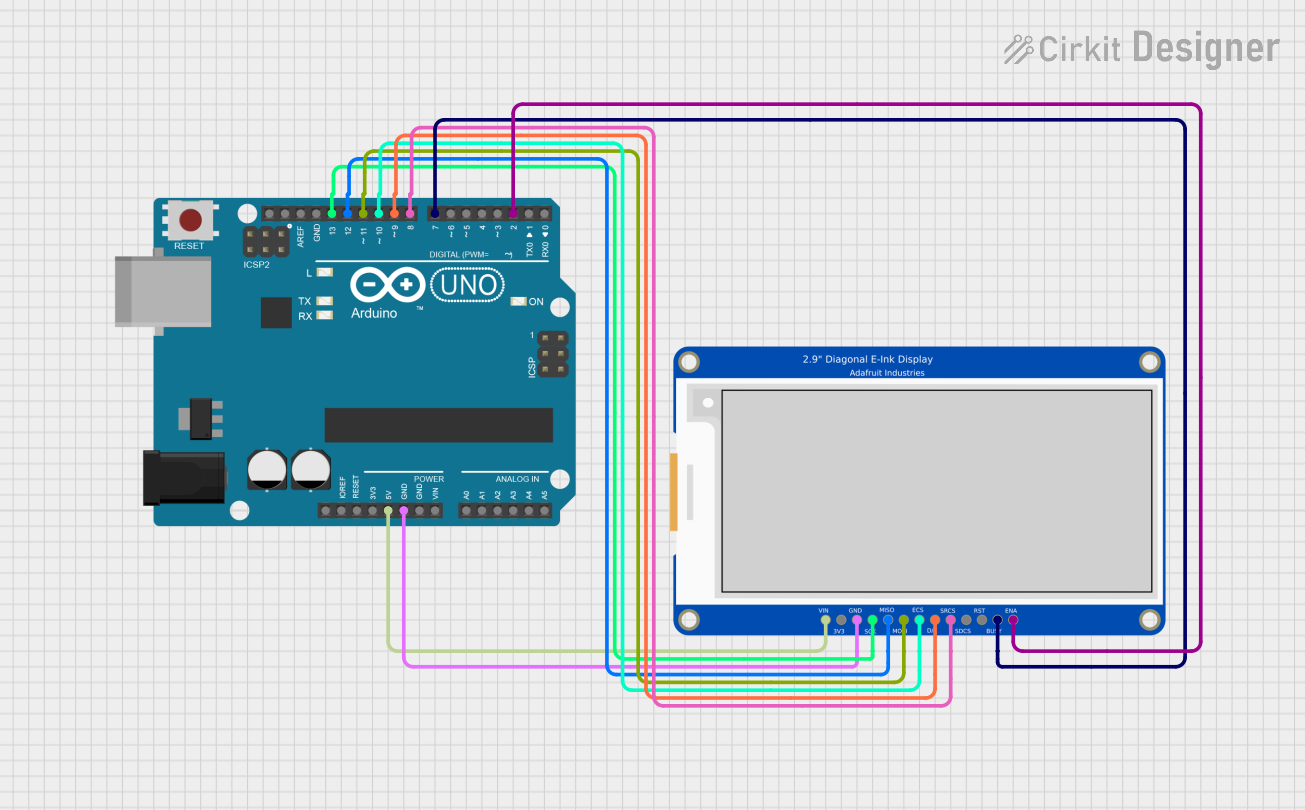 Open Project in Cirkit Designer
 Open Project in Cirkit Designer
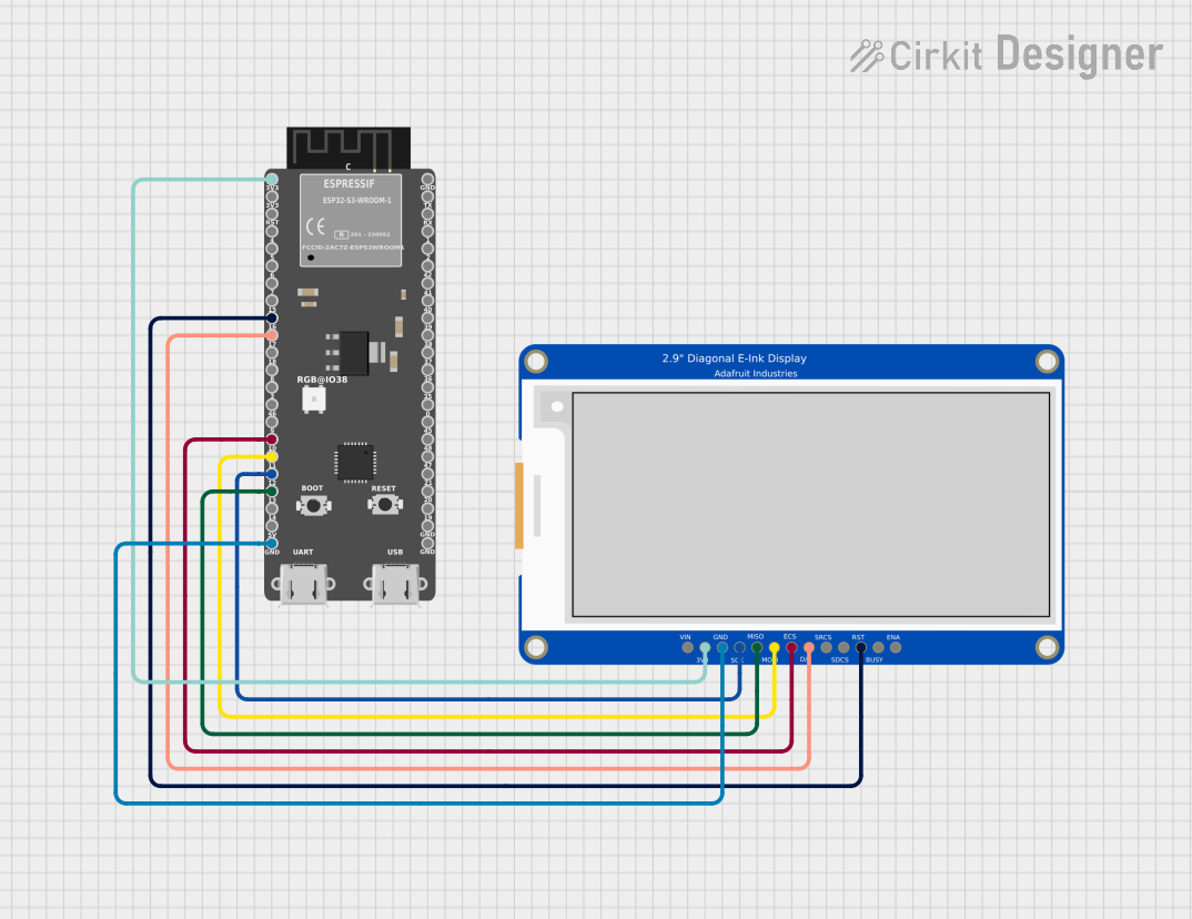 Open Project in Cirkit Designer
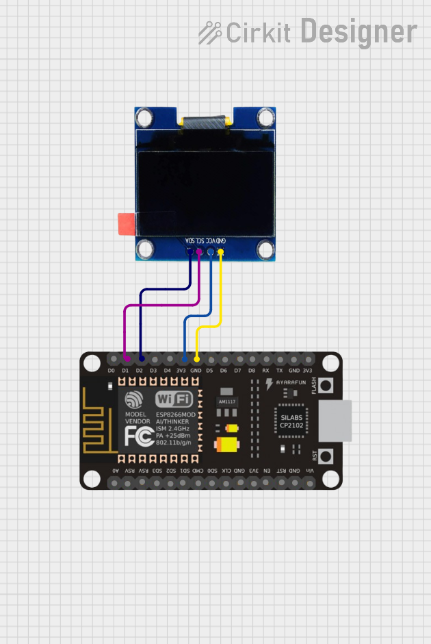 Open Project in Cirkit Designer
Explore Projects Built with Adafruit 2.13in eInk Breakout Rev D
Open Project in Cirkit DesignerOpen Project in Cirkit DesignerOpen Project in Cirkit DesignerOpen Project in Cirkit DesignerCommon Applications
- Electronic shelf labels
- Smart home dashboards
- Low-power IoT devices
- Static signage and displays
- Wearable devices
Technical Specifications
The Adafruit 2.13in eInk Breakout Rev D is built for versatility and ease of use. Below are its key technical details:
Key Specifications
| Parameter | Value |
|---|---|
| Display Type | eInk (EPD - Electrophoretic Display) |
| Screen Size | 2.13 inches |
| Resolution | 250 x 122 pixels |
| Color | Black and White |
| Interface | SPI |
| Operating Voltage | 3.3V or 5V (logic level safe) |
| Power Consumption | ~20mA during refresh, ~0mA static |
| Refresh Time | ~2 seconds |
| Dimensions | 61mm x 30mm x 4mm |
Pin Configuration
The breakout board features a 7-pin header for easy connection. Below is the pinout:
| Pin Name | Description |
|---|---|
| VIN | Power input (3.3V or 5V) |
| GND | Ground |
| SCK | SPI Clock |
| MOSI | SPI Data Input |
| CS | Chip Select (Active Low) |
| DC | Data/Command Control |
| RST | Reset (Active Low) |
| BUSY | Busy Signal (High when refreshing) |
Usage Instructions
The Adafruit 2.13in eInk Breakout Rev D is straightforward to use with microcontrollers like the Arduino UNO. Below are the steps to integrate and use the display in your project.
Connecting the Display
- Power Supply: Connect the
VINpin to the 5V or 3.3V pin of your microcontroller andGNDto ground. - SPI Interface: Connect the
SCKandMOSIpins to the corresponding SPI pins on your microcontroller. - Control Pins:
- Connect
CSto a digital pin (e.g., D10 on Arduino UNO). - Connect
DCto another digital pin (e.g., D9). - Connect
RSTto a digital pin (e.g., D8). - Optionally, connect
BUSYto a digital pin (e.g., D7) to monitor the display's status.
- Connect
Arduino Example Code
Below is an example of how to use the display with an Arduino UNO. This code uses the Adafruit GFX and Adafruit EPD libraries, which can be installed via the Arduino Library Manager.
#include <Adafruit_GFX.h>    // Core graphics library
#include <Adafruit_EPD.h>    // eInk display library

// Pin definitions
#define EPD_CS    10  // Chip Select
#define EPD_DC     9  // Data/Command
#define EPD_RST    8  // Reset
#define EPD_BUSY   7  // Busy

// Create an instance of the display
Adafruit_SSD1681 display(250, 122, EPD_DC, EPD_RST, EPD_CS, -1, EPD_BUSY);

void setup() {
  // Initialize serial communication for debugging
  Serial.begin(115200);
  Serial.println("Initializing eInk display...");

  // Initialize the display
  display.begin();

  // Clear the display
  display.clearBuffer();
  display.display();

  // Draw text on the display
  display.setTextSize(1);  // Set text size
  display.setTextColor(EPD_BLACK);  // Set text color
  display.setCursor(10, 10);  // Set cursor position
  display.println("Hello, eInk!");  // Print text

  // Update the display
  display.display();
}

void loop() {
  // Nothing to do here
}
Important Considerations
- Refresh Time: The display takes approximately 2 seconds to refresh. Avoid frequent updates to minimize power consumption and extend the display's lifespan.
- Power Consumption: The display consumes power only during refresh. Ensure your power supply can handle the ~20mA peak current during updates.
- Temperature Range: eInk displays may not perform well in extreme temperatures. Use within the recommended range of 0°C to 50°C.
Troubleshooting and FAQs
Common Issues
Display Not Refreshing:
- Ensure all connections are secure and match the pinout table.
- Verify that the
CS,DC, andRSTpins are correctly defined in your code. - Check the
BUSYpin to ensure the display is not still refreshing.
Blank Screen:
- Confirm that the
VINpin is receiving the correct voltage (3.3V or 5V). - Ensure the Adafruit GFX and EPD libraries are installed and up to date.
- Confirm that the
Slow Refresh:
- This is a normal characteristic of eInk displays. Avoid frequent updates to improve performance.
FAQs
Q: Can I use this display with a 3.3V microcontroller?
A: Yes, the breakout board is logic level safe and works with both 3.3V and 5V systems.
Q: How do I display images?
A: Convert your image to a monochrome bitmap (1-bit depth) and use the Adafruit GFX library to render it on the display.
Q: Can I use this display outdoors?
A: Yes, the high contrast of eInk displays makes them readable in bright sunlight. However, avoid exposing the display to extreme temperatures or moisture.
Q: How long does the image stay on the screen without power?
A: The image can remain visible for months without power, depending on environmental conditions.
By following this documentation, you can effectively integrate and use the Adafruit 2.13in eInk Breakout Rev D in your projects.