How to Use LilyTwinkle: Examples, Pinouts, and Specs
Introduction
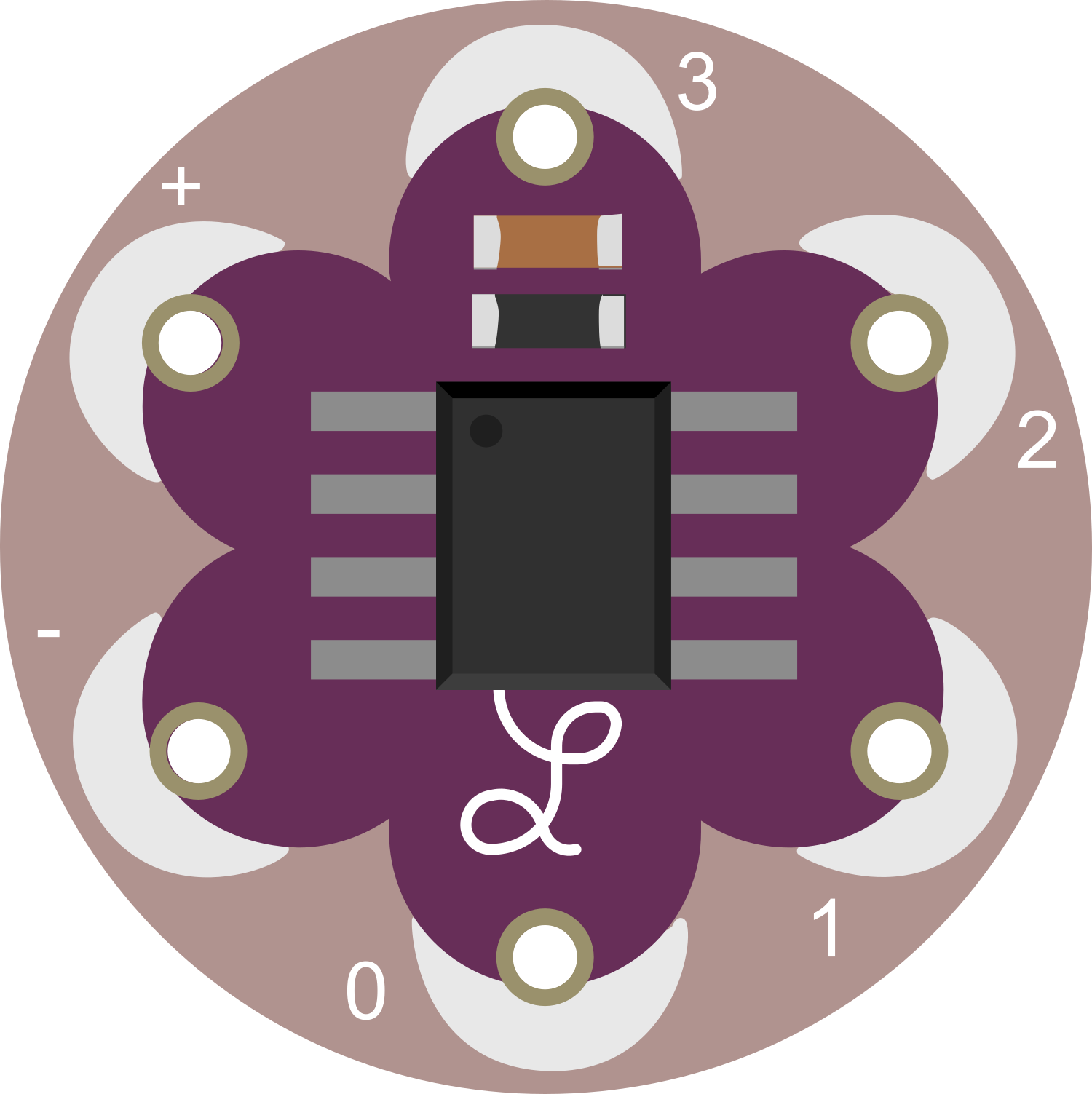
The LilyTwinkle is a compact, wearable microcontroller board designed around the ATtiny85 chip. It is equipped with an onboard RGB LED, a power switch, and a programming interface, making it an ideal choice for interactive wearable projects that require illumination. Its small form factor and low power consumption allow it to be seamlessly integrated into textiles and wearable garments, providing a platform for fashion technology, smart accessories, and educational purposes.
Explore Projects Built with LilyTwinkle
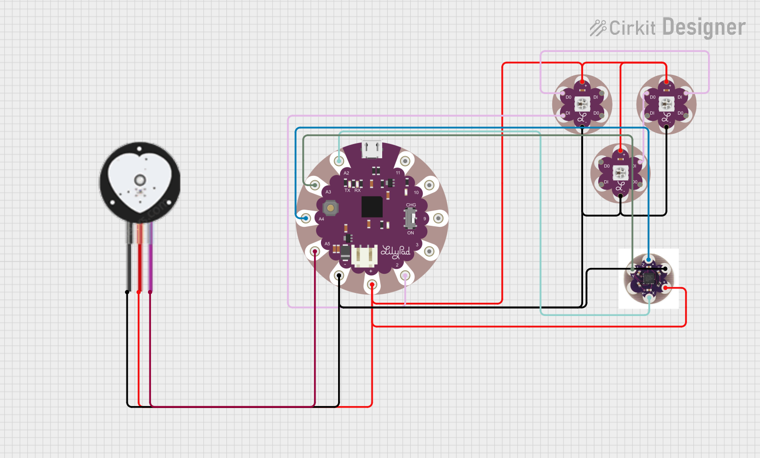

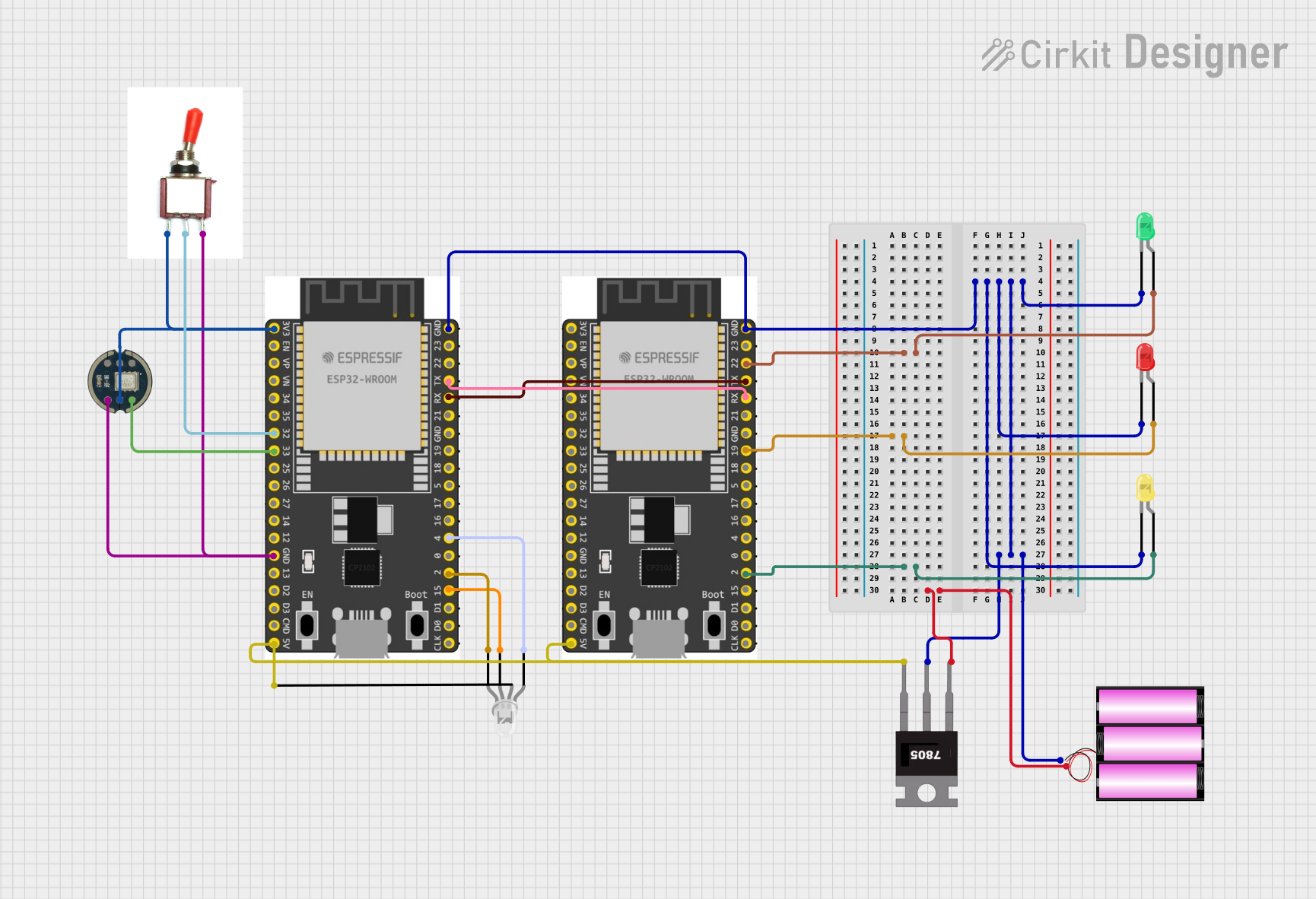

Explore Projects Built with LilyTwinkle
Common Applications and Use Cases
- Wearable electronics (e.g., smart clothing, interactive costumes)
- Educational projects to teach basic electronics and programming
- Prototyping for fashion technology
- Interactive art installations
- Small, battery-powered RGB LED displays
Technical Specifications
Key Technical Details
- Microcontroller: ATtiny85
- Operating Voltage: 3V to 5V
- Input Voltage: 3V to 5V (via battery holder)
- Output: Onboard RGB LED
- Programming Interface: ISP header for use with an external programmer
- I/O Pins: 5 usable I/O pins
- Flash Memory: 8 KB (of which ~2 KB used by bootloader)
- SRAM: 512 bytes
- EEPROM: 512 bytes
- Clock Speed: 8 MHz internal oscillator
Pin Configuration and Descriptions
| Pin Number | Name | Description |
|---|---|---|
| 1 | VCC | Power supply (3V to 5V) |
| 2 | GND | Ground connection |
| 3 | PB3 | Digital I/O, Analog Input, PWM |
| 4 | PB4 | Digital I/O, Analog Input, PWM, used for onboard RGB LED |
| 5 | PB1 | Digital I/O, Analog Input, PWM |
| 6 | PB2 | Digital I/O, Analog Input, PWM, used for programming |
| 7 | PB5 | Reset pin, used for programming |
| 8 | PB0 | Digital I/O, Analog Input, PWM |
Usage Instructions
How to Use the LilyTwinkle in a Circuit
- Powering the LilyTwinkle: Connect a 3V coin cell battery or other power sources to the VCC and GND pins.
- Programming the LilyTwinkle: Use an ISP programmer connected to the ISP header to upload your code.
- Connecting Additional Components: Use the I/O pins to connect sensors, actuators, or other LEDs. Ensure that the components are compatible with the operating voltage and current limitations of the LilyTwinkle.
Important Considerations and Best Practices
- Always verify the polarity of your power connections to prevent damage to the LilyTwinkle.
- When sewing the LilyTwinkle into fabric, use conductive thread and ensure secure connections.
- Avoid placing heavy stress on the board to prevent cracking or breaking.
- To minimize power consumption, use sleep modes in your code when the microcontroller is idle.
- Keep the LilyTwinkle away from moisture or use waterproofing techniques if the project will be exposed to water.
Troubleshooting and FAQs
Common Issues
- LilyTwinkle not powering on: Check the battery and ensure proper orientation. Verify that the VCC and GND connections are secure.
- Onboard RGB LED not lighting up: Ensure that the LED is correctly programmed and that the PB4 pin is not being used for other purposes that could interfere with the LED operation.
- Difficulty uploading code: Check the connections to the ISP programmer and ensure that the correct board and programmer settings are selected in your programming software.
Solutions and Tips for Troubleshooting
- If the LilyTwinkle does not power on, try a different power source or check for shorts in the circuit.
- For issues with the onboard RGB LED, review your code to ensure that the correct pin is being addressed and that the LED is being driven with the appropriate PWM signal.
- When having trouble uploading code, double-check the programmer connections and ensure that the LilyTwinkle's reset pin is functioning correctly.
FAQs
Q: Can I reprogram the LilyTwinkle without an ISP programmer? A: No, the LilyTwinkle requires an ISP programmer for code uploading.
Q: Is the LilyTwinkle washable? A: The LilyTwinkle itself is not washable. If integrated into clothing, the electronics should be removable or properly waterproofed.
Q: How do I extend the battery life of my project? A: Utilize sleep modes in your code, reduce the brightness of LEDs, and use power-efficient components.
Q: Can I connect multiple LilyTwinkles together? A: Yes, you can connect multiple LilyTwinkles in a project, but ensure that each one is properly powered and that the I/O pins are not overloaded.
Example Code for Arduino UNO
Below is an example code snippet for controlling the onboard RGB LED of the LilyTwinkle using an Arduino UNO. This code assumes you have connected the LilyTwinkle to the Arduino UNO for programming purposes.
// Define the pin connected to the onboard RGB LED
const int ledPin = 4; // PB4 on the LilyTwinkle

void setup() {
  // Set the LED pin as an output
  pinMode(ledPin, OUTPUT);
}

void loop() {
  // Turn on the LED
  digitalWrite(ledPin, HIGH);
  delay(1000); // Wait for 1 second
  // Turn off the LED
  digitalWrite(ledPin, LOW);
  delay(1000); // Wait for 1 second
}
Remember to configure your programming environment for the ATtiny85 and use an ISP programmer to upload the code to the LilyTwinkle.