How to Use Pixhawk Output Pin: Examples, Pinouts, and Specs
Introduction
The Pixhawk Output Pin is a critical interface on the Pixhawk flight controller, designed to output signals to various peripherals. These pins are commonly used to control motors, servos, sensors, or communication devices in unmanned vehicles such as drones, rovers, and boats. By providing precise signal outputs, the Pixhawk Output Pin enables seamless control and data exchange, making it an essential component in autonomous systems.
Explore Projects Built with Pixhawk Output Pin
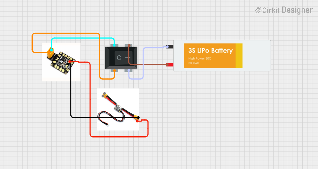


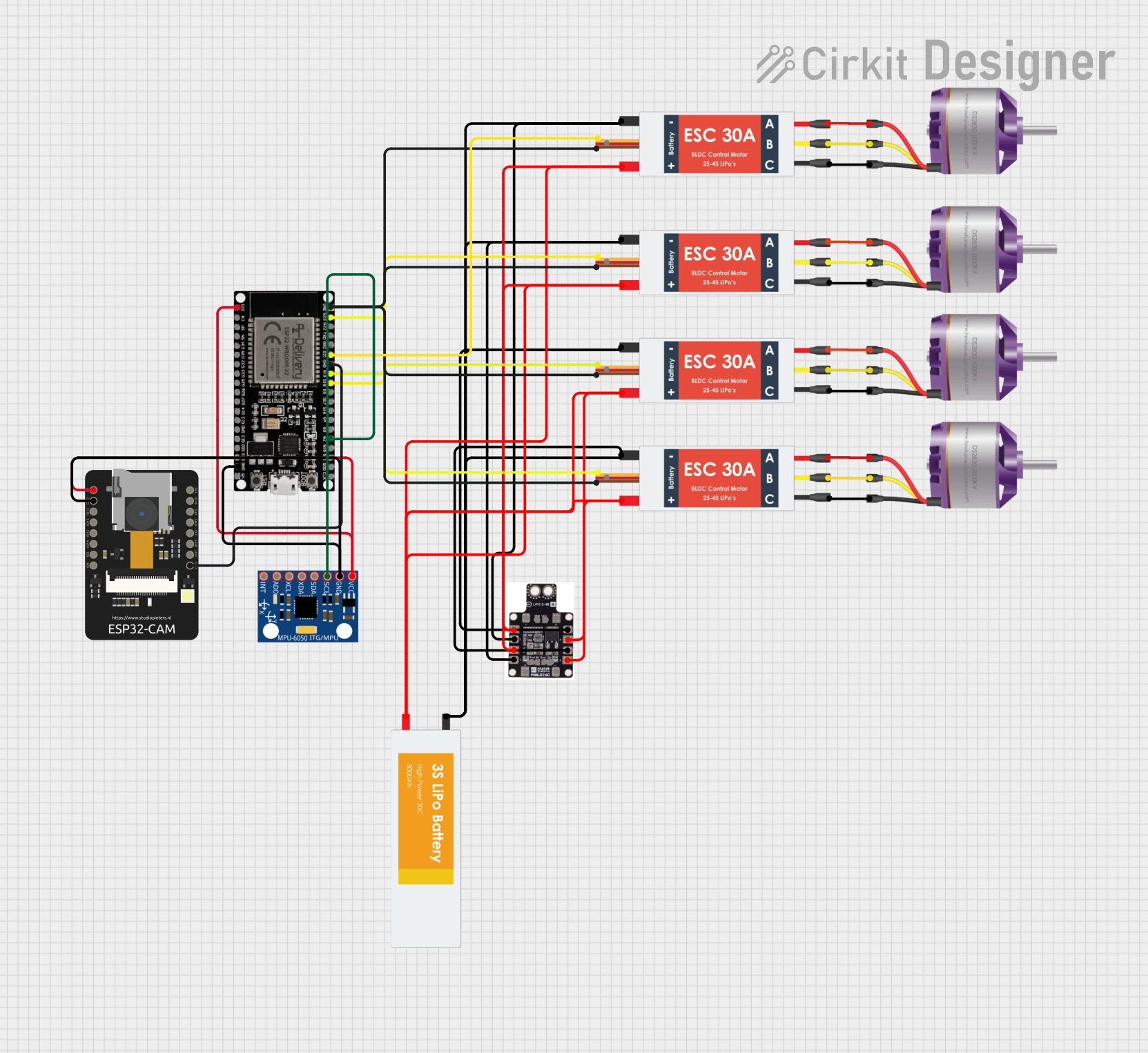
Explore Projects Built with Pixhawk Output Pin
Common Applications and Use Cases
- Controlling brushless motors via Electronic Speed Controllers (ESCs)
- Driving servos for gimbals, control surfaces, or robotic arms
- Sending signals to external devices like cameras or telemetry modules
- Enabling communication with other peripherals in UAVs, UGVs, and USVs
Technical Specifications
The Pixhawk Output Pins are part of the I/O PWM output rail, which is used to send Pulse Width Modulation (PWM) or Digital signals to connected devices. Below are the key technical details:
Key Technical Details
- Voltage Levels: 3.3V logic level (compatible with most peripherals)
- Maximum Current: 10mA per pin (logic signal only; external power required for high-current devices)
- Signal Type: PWM or Digital
- Number of Pins: Typically 8 main output pins (labeled as
MAIN), with additional auxiliary pins (AUX) depending on the Pixhawk model - Frequency Range: 50Hz to 400Hz (configurable for PWM signals)
- Connector Type: 3-pin servo connectors (Signal, Power, Ground)
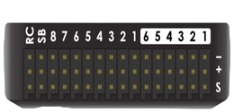
Pin Configuration and Descriptions
The Pixhawk Output Pins are organized into two groups: MAIN and AUX. The following table describes the pin layout:
MAIN Output Pins
| Pin Number | Signal Name | Description |
|---|---|---|
| MAIN 1 | PWM1 | Primary output for motor/servo 1 |
| MAIN 2 | PWM2 | Primary output for motor/servo 2 |
| MAIN 3 | PWM3 | Primary output for motor/servo 3 |
| MAIN 4 | PWM4 | Primary output for motor/servo 4 |
| MAIN 5 | PWM5 | Primary output for motor/servo 5 |
| MAIN 6 | PWM6 | Primary output for motor/servo 6 |
| MAIN 7 | PWM7 | Primary output for motor/servo 7 |
| MAIN 8 | PWM8 | Primary output for motor/servo 8 |
AUX Output Pins
| Pin Number | Signal Name | Description |
|---|---|---|
| AUX 1 | PWM9 | Auxiliary output for custom devices |
| AUX 2 | PWM10 | Auxiliary output for custom devices |
| AUX 3 | PWM11 | Auxiliary output for custom devices |
| AUX 4 | PWM12 | Auxiliary output for custom devices |
| AUX 5 | PWM13 | Auxiliary output for custom devices |
| AUX 6 | PWM14 | Auxiliary output for custom devices |
Note: The exact number of MAIN and AUX pins may vary depending on the Pixhawk model.
Usage Instructions
How to Use the Pixhawk Output Pin in a Circuit
- Connect the Peripheral:
- Use a 3-pin servo cable to connect the peripheral (e.g., motor, servo) to the desired output pin.
- Ensure the connections are correct: Signal (S), Power (+), and Ground (-).
- Power the Peripheral:
- The output pins only provide signal logic. Use an external power source (e.g., a Battery Eliminator Circuit or BEC) to power high-current devices like motors or servos.
- Configure the Output:
- Use the Pixhawk-compatible software (e.g., Mission Planner or QGroundControl) to assign functions to the output pins.
- Set the appropriate signal type (PWM or Digital) and frequency for the connected device.
- Test the Setup:
- Perform a bench test to verify that the peripheral responds correctly to the output signals.
Important Considerations and Best Practices
- Signal Compatibility: Ensure the connected device is compatible with the 3.3V logic level of the Pixhawk Output Pins.
- Power Supply: Do not rely on the Pixhawk to power high-current devices. Always use an external power source.
- Pin Assignment: Assign functions to the output pins carefully in the configuration software to avoid conflicts.
- Frequency Settings: Match the PWM frequency to the requirements of the connected device (e.g., 50Hz for servos, 400Hz for ESCs).
Example: Controlling a Servo with Arduino UNO
If you are using an Arduino UNO to simulate or test the Pixhawk Output Pin functionality, you can use the following code:
#include <Servo.h> // Include the Servo library

Servo myServo; // Create a Servo object

void setup() {
  myServo.attach(9); // Attach the servo to pin 9 on the Arduino
  // Set the initial position of the servo to 90 degrees
  myServo.write(90);
}

void loop() {
  // Move the servo to 0 degrees
  myServo.write(0);
  delay(1000); // Wait for 1 second

  // Move the servo to 180 degrees
  myServo.write(180);
  delay(1000); // Wait for 1 second
}
Note: Replace pin
9with the appropriate pin number if testing with a different setup.
Troubleshooting and FAQs
Common Issues and Solutions
Peripheral Not Responding:
- Cause: Incorrect wiring or configuration.
- Solution: Double-check the wiring (Signal, Power, Ground) and ensure the output pin is correctly assigned in the configuration software.
Signal Voltage Mismatch:
- Cause: The connected device requires a higher logic voltage (e.g., 5V).
- Solution: Use a logic level shifter to convert the 3.3V signal to 5V.
No Power to Peripheral:
- Cause: The peripheral is not receiving power.
- Solution: Ensure an external power source is connected to the power rail.
PWM Frequency Issues:
- Cause: The frequency is not set correctly for the device.
- Solution: Adjust the PWM frequency in the configuration software to match the device's requirements.
FAQs
Q1: Can I use the Pixhawk Output Pins to power my servos directly?
A1: No, the Pixhawk Output Pins only provide signal logic. Use an external power source to power servos or other high-current devices.
Q2: How do I know which pin to use for a specific motor or servo?
A2: Assign the desired function to the output pin in the configuration software (e.g., Mission Planner). Refer to the pin layout table for guidance.
Q3: Can I use the AUX pins for motor control?
A3: Yes, AUX pins can be used for motor control or other custom functions, depending on the configuration.
Q4: What is the maximum number of devices I can connect to the Pixhawk Output Pins?
A4: The number depends on the available MAIN and AUX pins on your Pixhawk model. For example, a standard Pixhawk 4 has 8 MAIN and 6 AUX pins, allowing up to 14 devices.