Cirkit Designer Logo
Cirkit Designer
Your all-in-one circuit design IDE
Home / 
Component Documentation

How to Use MT3608 Boost Converter: Examples, Pinouts, and Specs

Image of MT3608 Boost Converter
Cirkit Designer LogoDesign with MT3608 Boost Converter in Cirkit Designer

Introduction

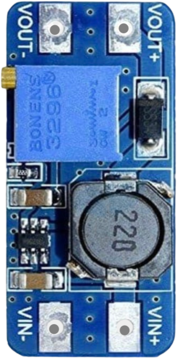
The MT3608 is a high-efficiency DC-DC boost converter designed to step up a lower input voltage to a higher output voltage. This component is widely used in battery-powered applications where a stable and adjustable higher voltage is required. Its compact design, adjustable output voltage, and high efficiency make it a versatile choice for powering devices such as LEDs, microcontrollers, and small motors.

Explore Projects Built with MT3608 Boost Converter

Use Cirkit Designer to design, explore, and prototype these projects online. Some projects support real-time simulation. Click "Open Project" to start designing instantly!
Voltage Regulation System with MT3608 Boost and LM2596 Buck Converters
Image of solar system router ups: A project utilizing MT3608 Boost Converter in a practical application
This circuit consists of two MT3608 boost converters and an LM2596 step-down module, each connected to separate 12V power supplies. The MT3608 modules are configured to step up the voltage from their respective power supplies, while the LM2596 module steps down the voltage from a 12V battery. Diodes are used to ensure correct current flow direction, potentially for protection or isolation between different parts of the circuit.
Cirkit Designer LogoOpen Project in Cirkit Designer
Battery-Powered DC Motor Control with USB Charging and LED Indicator
Image of lumantas: A project utilizing MT3608 Boost Converter in a practical application
This circuit is designed to charge a Li-ion battery and power a DC motor and a 12V LED. The TP4056 module manages the battery charging process, while the PowerBoost 1000 and MT3608 boost converters step up the voltage to drive the motor and LED, respectively. Two rocker switches control the power flow to the LED and the charging circuit.
Cirkit Designer LogoOpen Project in Cirkit Designer
ESP32-Powered Obstacle Avoidance Robot with IR and Ultrasonic Sensors
Image of projcememek: A project utilizing MT3608 Boost Converter in a practical application
This circuit features a 18650 Li-Ion battery connected to a TP4056 charging module, which in turn is connected to an MT3608 boost converter to step up the voltage. The output of the MT3608 powers an ESP32 microcontroller, a TCRT 5000 IR sensor, an HC-SR04 ultrasonic sensor, and an MG996R servo motor. The ESP32 is configured to control the servo motor via GPIO 27 and to receive input signals from the IR sensor and ultrasonic sensor through GPIO 14 and GPIO 13, respectively.
Cirkit Designer LogoOpen Project in Cirkit Designer
Battery-Powered Boost Converter with USB Type-C and BMS
Image of Weird Case: A project utilizing MT3608 Boost Converter in a practical application
This circuit is a power management and conversion system that includes a boost converter, battery management system (BMS), and various MOSFETs and passive components. It is designed to regulate and boost the voltage from a 2000mAh battery, providing stable power output through a USB Type C interface. The circuit also includes protection and switching mechanisms to ensure safe and efficient power delivery.
Cirkit Designer LogoOpen Project in Cirkit Designer

Explore Projects Built with MT3608 Boost Converter

Use Cirkit Designer to design, explore, and prototype these projects online. Some projects support real-time simulation. Click "Open Project" to start designing instantly!
Image of solar system router ups: A project utilizing MT3608 Boost Converter in a practical application
Voltage Regulation System with MT3608 Boost and LM2596 Buck Converters
This circuit consists of two MT3608 boost converters and an LM2596 step-down module, each connected to separate 12V power supplies. The MT3608 modules are configured to step up the voltage from their respective power supplies, while the LM2596 module steps down the voltage from a 12V battery. Diodes are used to ensure correct current flow direction, potentially for protection or isolation between different parts of the circuit.
Cirkit Designer LogoOpen Project in Cirkit Designer
Image of lumantas: A project utilizing MT3608 Boost Converter in a practical application
Battery-Powered DC Motor Control with USB Charging and LED Indicator
This circuit is designed to charge a Li-ion battery and power a DC motor and a 12V LED. The TP4056 module manages the battery charging process, while the PowerBoost 1000 and MT3608 boost converters step up the voltage to drive the motor and LED, respectively. Two rocker switches control the power flow to the LED and the charging circuit.
Cirkit Designer LogoOpen Project in Cirkit Designer
Image of projcememek: A project utilizing MT3608 Boost Converter in a practical application
ESP32-Powered Obstacle Avoidance Robot with IR and Ultrasonic Sensors
This circuit features a 18650 Li-Ion battery connected to a TP4056 charging module, which in turn is connected to an MT3608 boost converter to step up the voltage. The output of the MT3608 powers an ESP32 microcontroller, a TCRT 5000 IR sensor, an HC-SR04 ultrasonic sensor, and an MG996R servo motor. The ESP32 is configured to control the servo motor via GPIO 27 and to receive input signals from the IR sensor and ultrasonic sensor through GPIO 14 and GPIO 13, respectively.
Cirkit Designer LogoOpen Project in Cirkit Designer
Image of Weird Case: A project utilizing MT3608 Boost Converter in a practical application
Battery-Powered Boost Converter with USB Type-C and BMS
This circuit is a power management and conversion system that includes a boost converter, battery management system (BMS), and various MOSFETs and passive components. It is designed to regulate and boost the voltage from a 2000mAh battery, providing stable power output through a USB Type C interface. The circuit also includes protection and switching mechanisms to ensure safe and efficient power delivery.
Cirkit Designer LogoOpen Project in Cirkit Designer

Common Applications:

  • Powering microcontrollers (e.g., Arduino, ESP32) from lower voltage sources
  • Driving LED strips or high-power LEDs
  • Boosting voltage from single-cell lithium-ion batteries
  • Portable electronics and DIY projects
  • Solar-powered systems

Technical Specifications

Key Technical Details:

Parameter Value
Input Voltage Range 2V to 24V
Output Voltage Range 2V to 28V (adjustable via potentiometer)
Maximum Output Current 2A (depends on input voltage and load)
Efficiency Up to 93%
Switching Frequency 1.2 MHz
Dimensions ~36mm x 17mm x 6mm

Pin Configuration and Descriptions:

Pin Name Description
VIN Input voltage pin. Connect the positive terminal of the input power source.
GND Ground pin. Connect to the negative terminal of the input power source.
VOUT Output voltage pin. Provides the boosted voltage.

Usage Instructions

How to Use the MT3608 in a Circuit:

  1. Connect the Input Voltage:

    • Connect the positive terminal of your power source (e.g., battery) to the VIN pin.
    • Connect the negative terminal of your power source to the GND pin.
  2. Adjust the Output Voltage:

    • Use the onboard potentiometer to adjust the output voltage.
    • Turn the potentiometer clockwise to increase the output voltage and counterclockwise to decrease it.
    • Use a multimeter to measure the output voltage at the VOUT pin while adjusting.
  3. Connect the Load:

    • Connect the positive terminal of your load to the VOUT pin.
    • Connect the negative terminal of your load to the GND pin.

Important Considerations:

  • Input Voltage Limitations: Ensure the input voltage is within the 2V to 24V range.
  • Output Voltage Adjustment: Do not exceed the maximum output voltage of 28V.
  • Current Limitations: The maximum output current is 2A, but this depends on the input voltage and load. Exceeding this limit may damage the module.
  • Heat Dissipation: For high current loads, the module may heat up. Consider adding a heatsink or improving ventilation.

Example: Using MT3608 with Arduino UNO

The MT3608 can be used to power an Arduino UNO from a 3.7V lithium-ion battery. Below is an example circuit and code to blink an LED using the Arduino UNO powered by the MT3608.

Circuit Connections:

  1. Connect the 3.7V lithium-ion battery to the VIN and GND pins of the MT3608.
  2. Adjust the MT3608 output voltage to 5V using the potentiometer.
  3. Connect the VOUT pin of the MT3608 to the 5V pin of the Arduino UNO.
  4. Connect the GND pin of the MT3608 to the GND pin of the Arduino UNO.

Arduino Code:

// Simple LED Blink Example
// This code blinks an LED connected to pin 13 of the Arduino UNO.

void setup() {
  pinMode(13, OUTPUT); // Set pin 13 as an output pin
}

void loop() {
  digitalWrite(13, HIGH); // Turn the LED on
  delay(1000);            // Wait for 1 second
  digitalWrite(13, LOW);  // Turn the LED off
  delay(1000);            // Wait for 1 second
}

Troubleshooting and FAQs

Common Issues:

  1. No Output Voltage:

    • Cause: Input voltage is too low or not connected properly.
    • Solution: Verify the input voltage is within the 2V to 24V range and check connections.
  2. Output Voltage Not Adjustable:

    • Cause: Potentiometer is damaged or not functioning.
    • Solution: Replace the potentiometer or check for physical damage.
  3. Module Overheating:

    • Cause: Excessive current draw or poor ventilation.
    • Solution: Reduce the load current or add a heatsink to the module.
  4. Output Voltage Drops Under Load:

    • Cause: Input power source cannot supply enough current.
    • Solution: Use a power source with a higher current rating.

FAQs:

  • Q: Can the MT3608 step down voltage?
    A: No, the MT3608 is a boost converter and can only step up voltage.

  • Q: How do I know the output voltage is stable?
    A: Use a multimeter to measure the output voltage under load. Ensure the input power source is stable.

  • Q: Can I use the MT3608 to power a Raspberry Pi?
    A: While it is possible, the Raspberry Pi's high current requirements may cause the MT3608 to overheat. Use with caution and ensure proper cooling.


This documentation provides a comprehensive guide to using the MT3608 Boost Converter effectively in your projects.