
How to Use 5 mm RGB LED, Common Anode (R-B-G Pin Order): Examples, Pinouts, and Specs

 Design with 5 mm RGB LED, Common Anode (R-B-G Pin Order) in Cirkit Designer
Introduction
The 5 mm RGB LED, Common Anode, is a versatile light-emitting diode that combines red, blue, and green LEDs into a single package. This component allows users to create a wide range of colors by adjusting the intensity of each LED. The "common anode" configuration means that all three LEDs share a single positive terminal, while the negative terminals for each color are controlled individually.
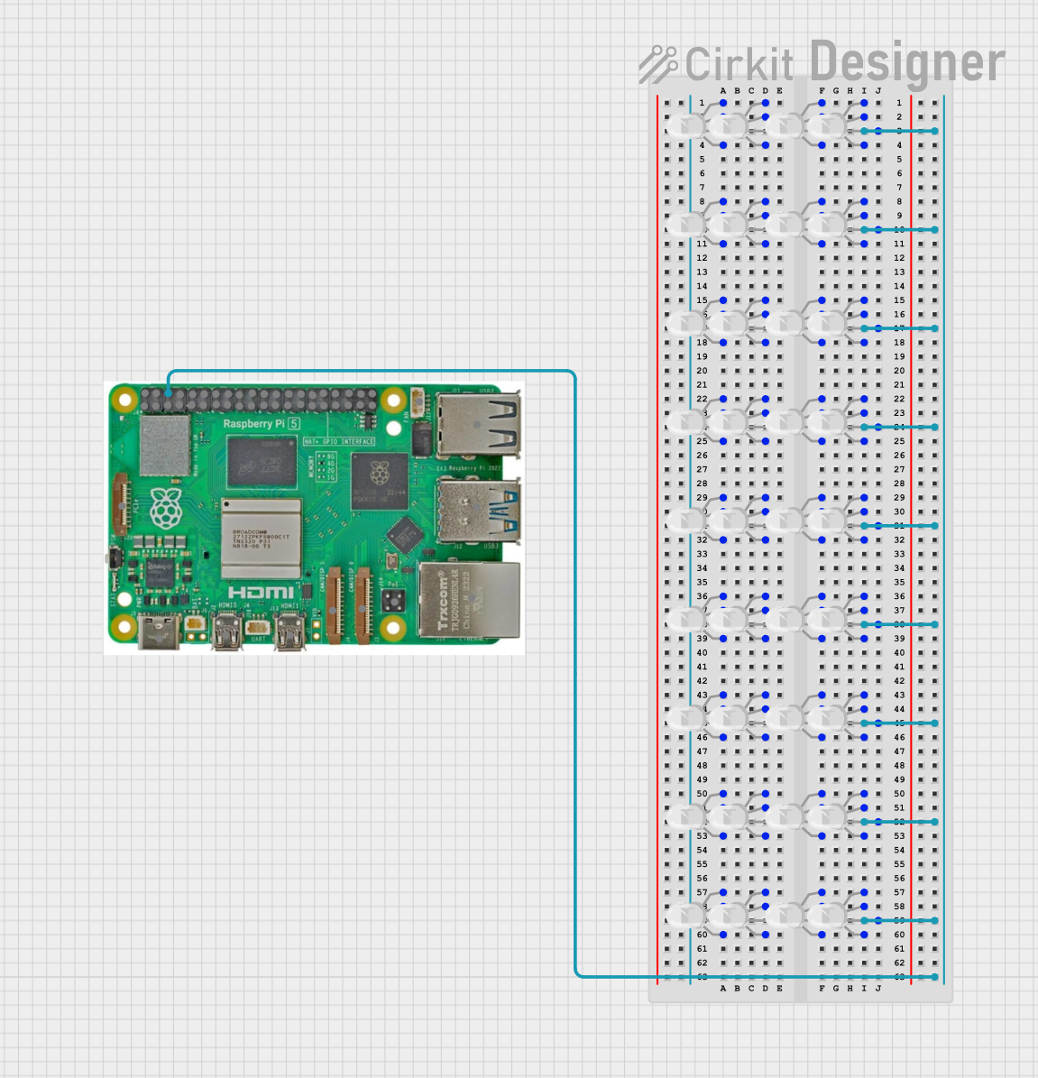
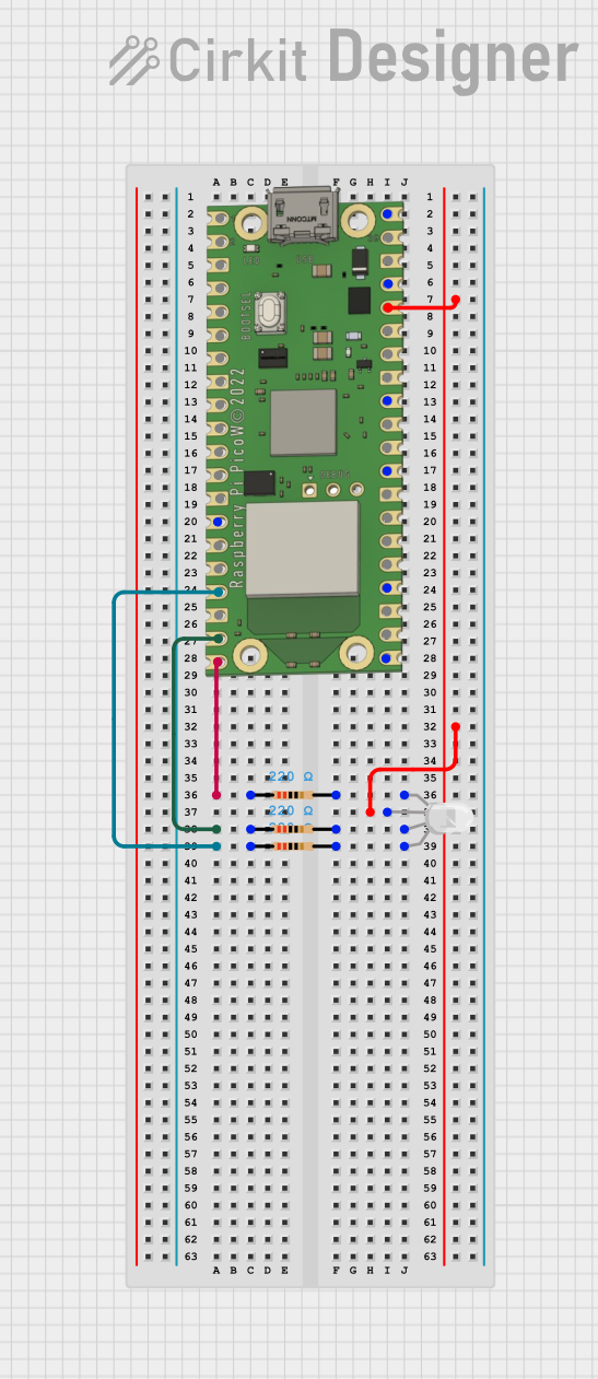
Explore Projects Built with 5 mm RGB LED, Common Anode (R-B-G Pin Order)
 Open Project in Cirkit Designer
 Open Project in Cirkit Designer
 Open Project in Cirkit Designer
 Open Project in Cirkit Designer
Explore Projects Built with 5 mm RGB LED, Common Anode (R-B-G Pin Order)
Open Project in Cirkit DesignerOpen Project in Cirkit DesignerOpen Project in Cirkit DesignerOpen Project in Cirkit DesignerCommon Applications and Use Cases
- Decorative lighting and displays
- Status indicators
- DIY electronics projects
- Color-mixing experiments
- Arduino and microcontroller-based projects
Technical Specifications
- Package Size: 5 mm diameter
- Configuration: Common Anode
- Forward Voltage:
- Red: 2.0V - 2.4V
- Green: 3.0V - 3.4V
- Blue: 3.0V - 3.4V
- Forward Current: 20 mA (per color)
- Maximum Power Dissipation: 75 mW (per color)
- Viewing Angle: 20° - 30°
- Pin Order: Common Anode, Red, Blue, Green (from longest to shortest pin)
Pin Configuration and Descriptions
| Pin Number | Pin Name | Description |
|---|---|---|
| 1 | Common Anode | Shared positive terminal for all three LEDs |
| 2 | Red Cathode | Negative terminal for the red LED |
| 3 | Blue Cathode | Negative terminal for the blue LED |
| 4 | Green Cathode | Negative terminal for the green LED |
Usage Instructions
How to Use the Component in a Circuit
- Connect the Common Anode: Attach the longest pin (common anode) to the positive voltage supply (e.g., 5V).
- Use Current-Limiting Resistors: Connect a resistor in series with each cathode (red, blue, and green) to limit the current and prevent damage to the LEDs. A typical resistor value is 220Ω for 5V systems.
- Control the Cathodes: Use switches, transistors, or microcontroller GPIO pins to control the cathodes. Adjusting the voltage or using PWM (Pulse Width Modulation) allows you to control the brightness of each color.
Important Considerations and Best Practices
- Resistor Selection: Choose appropriate resistor values based on the forward voltage and desired current. Use Ohm's Law: ( R = \frac{V_{supply} - V_{forward}}{I_{forward}} ).
- Avoid Overcurrent: Exceeding the maximum forward current (20 mA per color) can damage the LED.
- PWM for Color Mixing: Use PWM signals to adjust the brightness of each LED and create custom colors.
- Heat Management: Ensure proper ventilation if the LED is used at high brightness for extended periods.
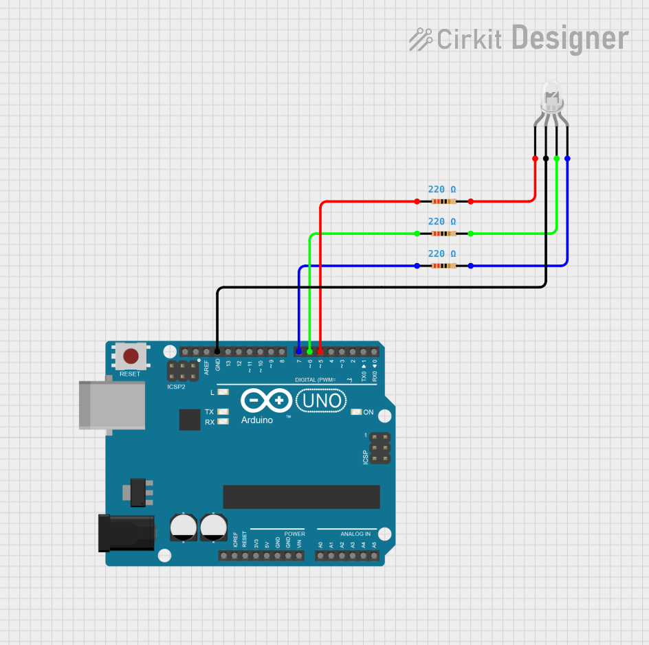
Example: Connecting to an Arduino UNO
Below is an example of how to connect and control the 5 mm RGB LED using an Arduino UNO.
Circuit Setup
- Connect the common anode pin to the 5V pin on the Arduino.
- Connect the red, blue, and green cathodes to Arduino digital pins (e.g., D9, D10, D11) through 220Ω resistors.
Arduino Code
// Define pins for the RGB LED cathodes
const int redPin = 9;   // Red cathode connected to pin D9
const int bluePin = 10; // Blue cathode connected to pin D10
const int greenPin = 11; // Green cathode connected to pin D11

void setup() {
  // Set RGB pins as outputs
  pinMode(redPin, OUTPUT);
  pinMode(bluePin, OUTPUT);
  pinMode(greenPin, OUTPUT);
}

void loop() {
  // Example: Cycle through colors
  setColor(255, 0, 0); // Red
  delay(1000);
  setColor(0, 255, 0); // Green
  delay(1000);
  setColor(0, 0, 255); // Blue
  delay(1000);
  setColor(255, 255, 0); // Yellow
  delay(1000);
  setColor(0, 255, 255); // Cyan
  delay(1000);
  setColor(255, 0, 255); // Magenta
  delay(1000);
  setColor(255, 255, 255); // White
  delay(1000);
}

// Function to set RGB LED color
void setColor(int redValue, int greenValue, int blueValue) {
  analogWrite(redPin, 255 - redValue);   // Invert value for common anode
  analogWrite(greenPin, 255 - greenValue); // Invert value for common anode
  analogWrite(bluePin, 255 - blueValue);  // Invert value for common anode
}
Troubleshooting and FAQs
Common Issues and Solutions
LED Not Lighting Up:
- Cause: Incorrect wiring or missing current-limiting resistors.
- Solution: Double-check the connections and ensure resistors are in place.
Incorrect Colors:
- Cause: Pins connected in the wrong order.
- Solution: Verify the pin order (Common Anode, Red, Blue, Green).
Dim or Flickering LEDs:
- Cause: Insufficient current or poor connections.
- Solution: Check resistor values and ensure secure connections.
Overheating:
- Cause: Excessive current through the LEDs.
- Solution: Use appropriate resistors to limit current.
FAQs
Can I use this LED with a 3.3V system? Yes, but you may need to adjust the resistor values to ensure proper current limiting.
Why do I need to invert PWM values for a common anode LED? In a common anode configuration, the cathodes are controlled by sinking current. A lower PWM value corresponds to higher brightness.
Can I control this LED without a microcontroller? Yes, you can use switches or potentiometers to manually control the cathodes.
This documentation provides all the necessary details to effectively use the 5 mm RGB LED, Common Anode, in your projects.