
How to Use PN532: Examples, Pinouts, and Specs
 Design with PN532 in Cirkit Designer
Introduction
The PN532 is a versatile NFC (Near Field Communication) controller that enables communication with NFC-enabled devices. It supports multiple modes of operation, including reader/writer, card emulation, and peer-to-peer communication. This flexibility makes the PN532 an ideal choice for a wide range of applications, such as:
- Contactless payment systems
- Access control and authentication
- Data exchange between NFC-enabled devices
- Smart posters and interactive kiosks
- IoT applications requiring short-range wireless communication
The PN532 is widely used due to its compatibility with various microcontrollers, including Arduino, and its support for multiple NFC protocols.
Explore Projects Built with PN532
 Open Project in Cirkit Designer
 Open Project in Cirkit Designer
 Open Project in Cirkit Designer
 Open Project in Cirkit Designer
Explore Projects Built with PN532
Open Project in Cirkit DesignerOpen Project in Cirkit DesignerOpen Project in Cirkit DesignerOpen Project in Cirkit DesignerTechnical Specifications
The PN532 is a highly integrated NFC controller with the following key specifications:
| Parameter | Value |
|---|---|
| Operating Voltage | 2.7V to 5.5V |
| Communication Interfaces | I²C, SPI, UART |
| Operating Frequency | 13.56 MHz |
| Supported Protocols | ISO/IEC 14443 Type A & B, FeliCa, NFC Forum Type 1-4 Tags |
| Maximum Communication Range | Up to 5 cm (depending on antenna design and environment) |
| Current Consumption | ~50 mA (active mode), ~100 µA (low-power mode) |
| Operating Temperature | -25°C to +85°C |
Pin Configuration and Descriptions
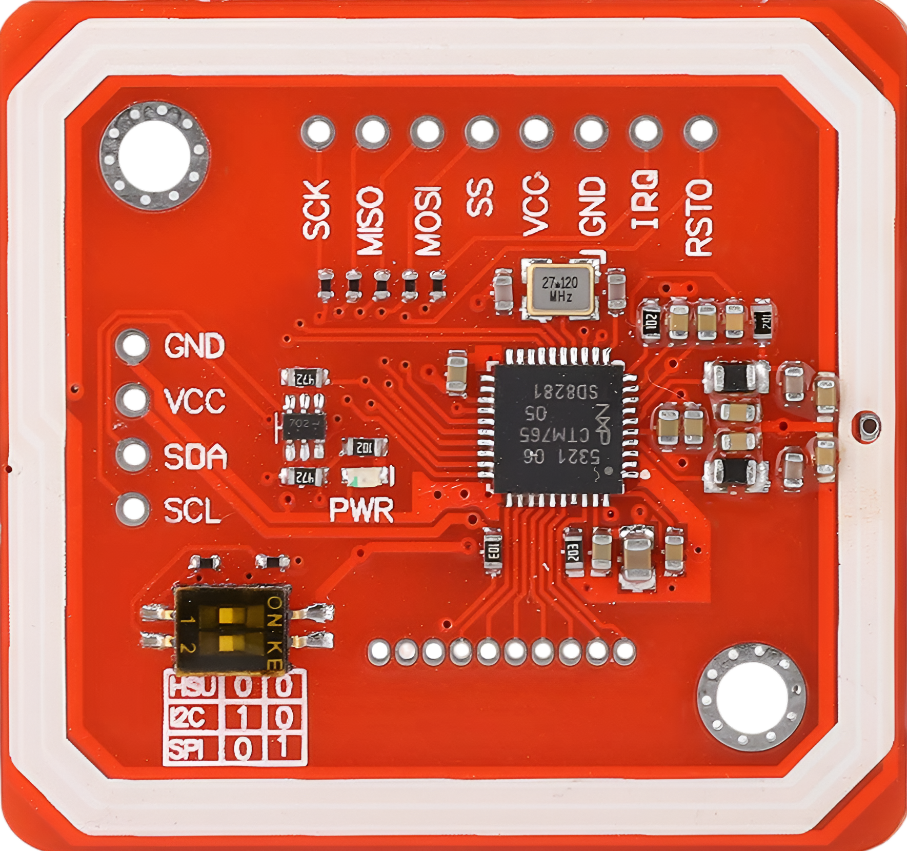
The PN532 module typically comes with the following pin configuration:
| Pin Name | Pin Number | Description |
|---|---|---|
| VCC | 1 | Power supply input (2.7V to 5.5V) |
| GND | 2 | Ground connection |
| SDA | 3 | I²C data line (used for I²C communication) |
| SCL | 4 | I²C clock line (used for I²C communication) |
| MOSI | 5 | Master Out Slave In (used for SPI communication) |
| MISO | 6 | Master In Slave Out (used for SPI communication) |
| SCK | 7 | Serial Clock (used for SPI communication) |
| NSS | 8 | SPI Chip Select (active low) |
| RX | 9 | UART Receive (used for UART communication) |
| TX | 10 | UART Transmit (used for UART communication) |
| IRQ | 11 | Interrupt Request (used to signal events to the microcontroller) |
| RST | 12 | Reset pin (active low, used to reset the module) |
Usage Instructions
Connecting the PN532 to an Arduino UNO
The PN532 can be interfaced with an Arduino UNO using I²C, SPI, or UART. Below is an example of connecting the PN532 using the I²C interface:
| PN532 Pin | Arduino UNO Pin |
|---|---|
| VCC | 5V |
| GND | GND |
| SDA | A4 |
| SCL | A5 |
| IRQ | Not connected |
| RST | Digital Pin 2 |
Example Code for I²C Communication
The following Arduino sketch demonstrates how to use the PN532 in I²C mode to read an NFC tag. This example uses the Adafruit_PN532 library, which can be installed via the Arduino Library Manager.
#include <Wire.h>
#include <Adafruit_PN532.h>

// Define the I²C pins for the PN532
#define SDA_PIN A4
#define SCL_PIN A5
#define RST_PIN 2

// Create an instance of the Adafruit_PN532 class
Adafruit_PN532 nfc(SDA_PIN, SCL_PIN);

void setup() {
  Serial.begin(9600); // Initialize serial communication
  Serial.println("Initializing PN532...");

  nfc.begin(); // Initialize the PN532 module

  // Check if the PN532 is connected
  uint32_t versiondata = nfc.getFirmwareVersion();
  if (!versiondata) {
    Serial.println("Didn't find PN532 module!");
    while (1); // Halt execution if the module is not found
  }

  // Display firmware version
  Serial.print("Found PN532 with firmware version: ");
  Serial.print((versiondata >> 16) & 0xFF, HEX);
  Serial.print('.');
  Serial.println((versiondata >> 8) & 0xFF, HEX);

  // Configure the module to read NFC tags
  nfc.SAMConfig();
  Serial.println("Waiting for an NFC tag...");
}

void loop() {
  uint8_t success;
  uint8_t uid[] = { 0 }; // Buffer to store the UID
  uint8_t uidLength;

  // Attempt to read an NFC tag
  success = nfc.readPassiveTargetID(PN532_MIFARE_ISO14443A, uid, &uidLength);

  if (success) {
    Serial.println("NFC tag detected!");

    // Print the UID of the tag
    Serial.print("UID Length: "); Serial.print(uidLength, DEC); Serial.println(" bytes");
    Serial.print("UID Value: ");
    for (uint8_t i = 0; i < uidLength; i++) {
      Serial.print(" 0x"); Serial.print(uid[i], HEX);
    }
    Serial.println();

    delay(1000); // Wait before scanning for another tag
  }
}
Important Considerations
- Ensure the PN532 module is powered with the correct voltage (2.7V to 5.5V).
- Use pull-up resistors (typically 4.7kΩ) on the SDA and SCL lines for I²C communication.
- Avoid placing the module near metal objects, as they can interfere with NFC communication.
- When using SPI or UART, ensure the correct pins are connected and configured in the code.
Troubleshooting and FAQs
Common Issues
PN532 module not detected:
- Ensure the wiring is correct and matches the selected communication interface.
- Verify that the module is powered and the voltage is within the specified range.
- Check for loose connections or damaged wires.
NFC tag not detected:
- Ensure the tag is within the communication range (typically up to 5 cm).
- Verify that the tag is compatible with the PN532 (e.g., ISO/IEC 14443 Type A or B).
- Check for interference from nearby metal objects or other electronic devices.
Incorrect UID or data:
- Ensure the PN532 is properly configured for the desired protocol.
- Verify that the library and firmware versions are compatible.
Tips for Troubleshooting
- Use a multimeter to check the voltage levels on the VCC and GND pins.
- Test the module with a different microcontroller or communication interface to isolate the issue.
- Refer to the Adafruit_PN532 library documentation for additional examples and troubleshooting steps.
By following this documentation, you can effectively integrate the PN532 into your projects and leverage its NFC capabilities for a variety of applications.