How to Use 3DR Radio: Examples, Pinouts, and Specs
3DR Radio Module Documentation
1. Introduction
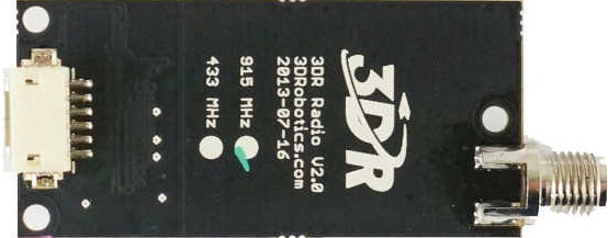
The 3DR Radio Module is a robust and reliable wireless communication module designed for transmitting and receiving data in real-time. Manufactured by 3DR, this module is widely used in drone and robotics applications, enabling remote control, telemetry, and data exchange between devices. It operates on the 915 MHz or 433 MHz frequency bands (depending on the model) and provides a long-range, low-latency communication link.
The 3DR Radio is commonly used in conjunction with flight controllers, such as the Pixhawk, and microcontrollers like the Arduino UNO. It is ideal for applications requiring telemetry data, such as monitoring drone flight parameters, controlling robots remotely, or transmitting sensor data over long distances.
Key Features:
- Long-range communication (up to several kilometers in open areas)
- Transparent serial link for easy integration
- Configurable baud rates and frequency settings
- Lightweight and compact design
- Plug-and-play compatibility with many flight controllers and microcontrollers
Common Applications:
- Drone telemetry and remote control
- Robotics communication
- Wireless sensor networks
- Remote monitoring systems
- IoT (Internet of Things) applications
2. Technical Specifications
The following table outlines the key technical specifications of the 3DR Radio Module:
| Parameter | Specification |
|---|---|
| Frequency Band | 915 MHz (North America) / 433 MHz (Europe) |
| Communication Protocol | Transparent Serial (UART) |
| Operating Voltage | 3.3V to 5V |
| Current Consumption | ~100 mA (transmitting) |
| Transmission Range | Up to 1-2 km (line of sight) |
| Data Rate | Up to 250 kbps |
| Antenna Connector | RP-SMA |
| Dimensions | 25 mm x 55 mm x 12 mm |
| Weight | ~15 g |
Pin Configuration and Descriptions
The 3DR Radio Module typically has a 6-pin header for interfacing. The pinout is as follows:
| Pin | Name | Description |
|---|---|---|
| 1 | GND | Ground connection |
| 2 | 5V | Power supply input (3.3V to 5V) |
| 3 | TX | Transmit data (UART TX) |
| 4 | RX | Receive data (UART RX) |
| 5 | CTS | Clear to Send (flow control, optional) |
| 6 | RTS | Request to Send (flow control, optional) |
3. Usage Instructions
Connecting the 3DR Radio Module to an Arduino UNO
To use the 3DR Radio Module with an Arduino UNO, follow these steps:
Hardware Connections:
- Connect the GND pin of the 3DR Radio to the GND pin of the Arduino.
- Connect the 5V pin of the 3DR Radio to the 5V pin of the Arduino.
- Connect the TX pin of the 3DR Radio to the RX pin of the Arduino.
- Connect the RX pin of the 3DR Radio to the TX pin of the Arduino.
Install Required Libraries:
- The 3DR Radio uses a transparent serial link, so no special libraries are required. You can use the Arduino's built-in
Seriallibrary for communication.
- The 3DR Radio uses a transparent serial link, so no special libraries are required. You can use the Arduino's built-in
Upload Code to the Arduino:
- Use the following example code to send and receive data via the 3DR Radio Module.
// Example code for using the 3DR Radio Module with Arduino UNO
// This code sends and receives data over the 3DR Radio link

void setup() {
  // Initialize Serial Monitor for debugging
  Serial.begin(9600); // Communication with PC
  // Initialize Serial1 for 3DR Radio communication
  Serial1.begin(57600); // Default baud rate for 3DR Radio
}

void loop() {
  // Check if data is available from the 3DR Radio
  if (Serial1.available()) {
    // Read data from the 3DR Radio and print it to the Serial Monitor
    String receivedData = Serial1.readString();
    Serial.print("Received: ");
    Serial.println(receivedData);
  }

  // Check if data is available from the Serial Monitor
  if (Serial.available()) {
    // Read data from the Serial Monitor and send it to the 3DR Radio
    String sendData = Serial.readString();
    Serial1.print(sendData);
  }
}
- Test the Communication:
- Open the Arduino Serial Monitor and set the baud rate to
9600. - Type a message in the Serial Monitor and press Enter. The message will be transmitted via the 3DR Radio.
- If another 3DR Radio is connected to a receiving device, the message will appear on the receiving end.
- Open the Arduino Serial Monitor and set the baud rate to
Important Considerations:
- Ensure both 3DR Radio modules (transmitter and receiver) are configured with the same baud rate and frequency settings.
- Use the Mission Planner software or a similar tool to configure the 3DR Radio parameters if needed.
- Avoid placing the module near sources of interference, such as high-power motors or metal objects.
4. Troubleshooting and FAQs
Common Issues and Solutions
| Issue | Possible Cause | Solution |
|---|---|---|
| No communication between modules | Mismatched baud rate or frequency settings | Ensure both modules are configured with the same baud rate and frequency. |
| Short communication range | Antenna not connected or interference | Check the antenna connection and avoid interference from nearby devices. |
| Module not powering on | Incorrect power supply | Ensure the module is powered with 3.3V to 5V. |
| Data corruption or loss | Poor signal quality or interference | Use a higher gain antenna or reduce the distance between modules. |
Frequently Asked Questions
Q1: Can I use the 3DR Radio Module with a Raspberry Pi?
A1: Yes, the 3DR Radio Module can be used with a Raspberry Pi. Connect the module to the Raspberry Pi's UART pins and configure the serial port for communication.
Q2: How do I configure the 3DR Radio settings?
A2: Use the Mission Planner software to configure the baud rate, frequency, and other parameters. Connect the module to your PC via a USB-to-serial adapter.
Q3: What is the maximum range of the 3DR Radio?
A3: The maximum range is up to 1-2 km in open areas with a clear line of sight. The range may vary depending on environmental conditions and antenna quality.
Q4: Can I use multiple 3DR Radios in the same area?
A4: Yes, you can use multiple 3DR Radios in the same area. Ensure each pair of modules operates on a unique frequency to avoid interference.
This documentation provides a comprehensive guide to using the 3DR Radio Module. Whether you're a beginner or an experienced user, this guide will help you integrate the module into your projects effectively. For further assistance, refer to the official 3DR documentation or community forums.
Explore Projects Built with 3DR Radio


Explore Projects Built with 3DR Radio